SR469-P5-HI-A20
Description
1. Product Overview
5A secondary CT input
High-Impedance ground fault option
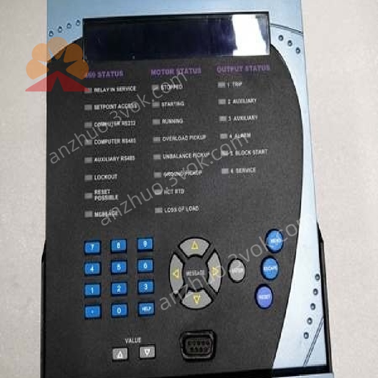
Enhanced LCD front panel
Complete motor thermal protection + RTD temperature monitoring
Built-in Modbus communication, analog outputs, programmable I/O
Industrial fan, pump, compressor, conveyor motors
Motor Control Centers (MCC)
Water treatment, oil & gas, power plant, mining, chemical industry
2. Main Features
Comprehensive Motor Protection
Overload protection (thermal memory)
Short circuit instantaneous & time delayed
Locked rotor protection
Phase unbalance, phase loss, phase reversal
Overvoltage / Undervoltage
Overfrequency / Underfrequency
High impedance ground fault protection
Temperature Monitoring
Support PT100 / PT1000 RTD sensors
Stator winding, bearing, ambient temperature monitoring
Configurable alarm and trip temperature thresholds
Measurement & Metering
3-phase current, voltage, power factor
Active power, reactive power, apparent power
Energy kWh, running time, motor start counter
I/O & Analog
Programmable digital inputs and relay outputs
4 isolated 4–20 mA analog outputs for remote SCADA
Communication
Front RS232 for local configuration
Rear RS485 Modbus RTU for network connection
Compatible with EnerVista 469 configuration software
Recording & Diagnostics
Fault event record, sequence of events log
Motor start/stop record, fault waveform capture
3. Technical Specifications
3.1 General Ratings
| Item | Specification |
|---|---|
| Model | SR469-P5-HI-A20 |
| Type | Digital Motor Protection Relay |
| CT Rated Secondary | 5 A |
| Control Supply Voltage | 70~265 VAC / 90~300 VDC |
| Frequency | 48 Hz ~ 62 Hz |
| Power Consumption | ≤15 VA |
| Mounting | Panel flush mount / Drawout type |
3.2 Analog Inputs
| Input | Parameter |
|---|---|
| Phase Current | 3-phase, 5A nominal |
| Ground Current | High impedance ground fault input |
| Voltage Input | 3-phase 0~120 VAC VT secondary |
| RTD Channels | Up to 6 channels (PT100/PT1000) |
3.3 Digital Input / Output
| Item | Spec |
|---|---|
| Digital Inputs | 8 channels opto-isolated |
| Relay Outputs | 5 Form C relay contacts |
| Contact Rating | 8A @ 250 VAC resistive load |
3.4 Analog Output
4 channels isolated 4~20 mA
Max load resistance: 500 Ω
Freely assignable: current, voltage, temperature, power etc.
3.5 Communication Interface
| Port | Protocol | Baud Rate |
|---|---|---|
| Front RS232 | Modbus RTU / ASCII | 9600~19200 bps |
| Rear RS485 | Modbus RTU | 1200~19200 bps |
3.5 Environmental Conditions
| Parameter | Range |
|---|---|
| Operating Temperature | -20°C ~ +60°C |
| Storage Temperature | -40°C ~ +85°C |
| Humidity | 5%~95% non-condensing |
| Vibration / Shock | IEC 60255 compliant |
| Protection Degree | IP20 front panel |
4. Functional Description
4.1 Protection Functions
Overload Protection: Thermal model simulation, with thermal memory, motor start inhibit
Short Circuit Protection: Instantaneous and definite time delay
Locked Rotor: Detect stall during starting and running
Unbalance & Phase Loss: Protect motor from single-phase operation
Ground Fault: High sensitive HI ground fault detection for insulation failure
Voltage/Frequency Protection: Prevent abnormal grid damage to motor
4.2 Thermal & RTD Protection
4.3 Monitoring & Data Recording
5. Installation & Wiring Instructions
5.1 Mechanical Installation
Install relay on control cabinet panel.
Reserve upper and lower ventilation space ≥50 mm.
The relay is drawout structure; pull the handle to take out the main body for maintenance.
5.2 Wiring Requirements
CT secondary must be shorted before wiring, strictly prohibit open circuit.
VT input must be equipped with fuse protection.
RTD cable use shielded twisted pair, single-point grounding.
RS485 communication use shielded twisted pair, add 120Ω terminal resistor at two ends of bus.
6. Front Panel Operation & LED Indication
LED Status Definition
| LED | Color | Status Meaning |
|---|---|---|
| PWR | Green | Power supply normal |
| RUN | Green | Motor in running status |
| TRIP | Red | Relay tripped due to fault |
| ALARM | Yellow | Abnormal alarm (over temperature, unbalance etc.) |
| COMM | Amber | Modbus communication data activity |
Operation Interface
Backlit LCD display
Numeric keypad and function keys for parameter setting, data viewing, fault reset.
7. Configuration Method
- Local Panel SettingManually set motor rated parameters, protection curves, I/O logic, communication address via front keypad.
- PC Software ConfigurationUse EnerVista 469 software:
Connect PC to relay front RS232 port
Edit parameters offline
Download configuration, upload fault records, upgrade firmware
8. Maintenance & Troubleshooting
Daily Maintenance
Regularly check wiring terminal looseness
Clean panel dust and ventilation holes
Backup relay configuration parameters
Periodically verify protection setting logic
Common Fault Handling
| Fault Phenomenon | Possible Cause | Solution |
|---|---|---|
| No power indicator | Control power supply abnormal | Check 70~265VAC power loop |
| Frequent overload trip | Parameter setting too strict / motor aging | Adjust overload curve; check motor temperature |
| Ground fault alarm | Cable insulation aging / wiring error | Inspect motor and cable insulation |
| Communication offline | Wrong baud rate / 485 wiring error | Check polarity, terminal resistance and address |
9. Ordering & Model Explanation
SR469: Series 469 Motor Relay
P5: 5A CT input
HI: High Impedance Ground Fault
A20: Enhanced panel + full I/O and analog output version
RS232 configuration cable
RS485 communication shielded cable
RTD shielded signal cable
10. Compliance & Certification
CE Certified (EMC / LVD)
UL 508 Industrial Control Equipment Certified
RoHS Compliant
Compliant with IEC 60255 Series Relay Standards
Get a Quote