IC695CRU320
Description
1. Product Overview

2. Key Features
Processor: 1.0 GHz Intel® Celeron® M microprocessor
Memory: 64 MB battery-backed user RAM + 64 MB non‑volatile flash user memory
Redundancy: Hot Standby (HSB) support; switchover time min. 3.133 ms, max. 1 logic scan
Communication: 2 × isolated serial ports (RS‑232, RS‑485)
Protocols: Modbus RTU Slave, SNP, Serial I/O
I/O Capacity: 32 K discrete bits (%I/%Q) + 32 K analog words (%AI/%AQ)
Programming: IEC 61131‑3 (Ladder, Structured Text, FBD, C)
Backplane: Dual bus (high‑speed PCI + serial for Series 90‑30 compatibility)
Diagnostics: 8 front‑panel LEDs for real‑time status monitoring
3. Technical Specifications
3.1 Processing & Memory
| Parameter | Value |
|---|---|
| Processor | 1.0 GHz Intel Celeron M |
| User RAM | 64 MB (battery‑backed) |
| User Flash | 64 MB (non‑volatile) |
| Max Program Blocks | 512 (128 KB max per block) |
| Symbol Memory | Configurable up to 64 MB |
| Real‑Time Clock | Battery‑backed (max drift 2 seconds/day) |
3.2 Redundancy
| Parameter | Value |
|---|---|
| Mode | Hot Standby (Primary/Backup) |
| Switchover Time | Min 3.133 ms; Max 1 logic scan |
| Sync Links | Up to 2 × IC695RMX128/228 |
| Data Transfer | Up to 2 MB per sync cycle |
3.3 Communication Interfaces
| Interface | Details |
|---|---|
| Serial Port 1 | RS‑232 (isolated), programming/SNP Slave |
| Serial Port 2 | RS‑485 (isolated), Modbus RTU Slave |
3.4 Electrical
| Parameter | Value |
|---|---|
| Backplane Power | +3.3 VDC @ 1.0 A; +5 VDC @ 1.2 A |
| Power Consumption | 8 W (typical) |
| Battery | CR2032 (3‑year life, memory retention) |
3.5 Environmental
| Parameter | Value |
|---|---|
| Operating Temp | 0 °C to +60 °C (free cooling) |
| Storage Temp | –40 °C to +85 °C |
| Humidity | 5–95% non‑condensing |
| Altitude | ≤2000 m |
3.6 Mechanical
| Parameter | Value |
|---|---|
| Form Factor | Two‑slot RX3i rack mount |
| Dimensions (H×W×D) | 170 × 150 × 60 mm |
| Weight | ~0.94 kg |
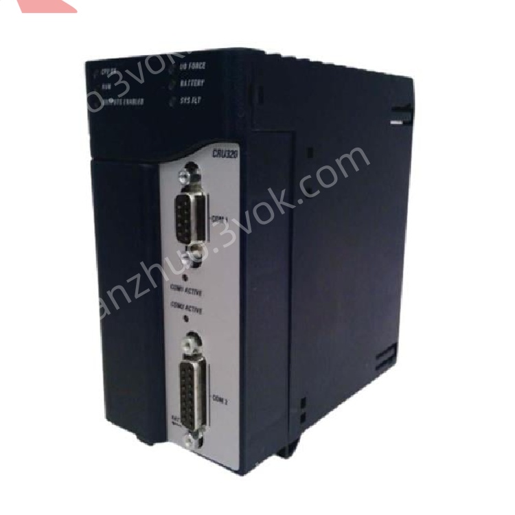
4. Panel Indicators & Controls
4.1 Front Panel LEDs
| LED | State | Meaning |
|---|---|---|
| CPU OK (Green) | Solid | Self‑test passed; module healthy |
| Blinking | Boot mode (firmware update) | |
| Off | Critical fault | |
| RUN (Green) | Solid | Executing user program |
| Blinking | Stop/Halt mode | |
| Off | Program halted | |
| OUTPUTS ENABLED (Green) | Solid | Output scan active |
| Off | Output scan disabled | |
| I/O FORCE (Yellow) | Solid | I/O override active |
| BATTERY (Yellow) | Blinking | Low battery |
| SYS FLT (Red) | Solid | System fault |
| Blinking | Minor fault/warning | |
| COM1/COM2 (Green/Yellow) | Solid | Link active |
| Blinking | Data activity |
4.2 Controls & Connectors
Serial Ports: COM1 (RS‑232), COM2 (RS‑485) (DB9 connectors)
Reset Button: Momentary press for warm reset; hold 5s for factory reset
Mode Switch: RUN/STOP (controls program execution)
5. Installation
5.1 Pre‑Installation
Disconnect all power from the RX3i rack and peripherals.
Verify target slot (CPU slot, typically Slot 1–2) is empty and backplane undamaged.
5.2 Rack Installation
Align module with RX3i rack’s CPU slot (occupies 2 slots).
Insert firmly until backplane connector is fully seated.
Secure module with front‑panel screws (torque 0.8–1.0 N·m).
Connect serial cables to COM1/COM2 as required.
Restore power; verify CPU OK LED illuminates.
5.3 Redundancy Setup
Install two IC695CRU320 modules (Primary/Backup) in separate racks.
Connect redundancy links via IC695RMX128/228 modules (fiber/copper).
Configure network settings in Proficy Machine Edition.
6. Programming & Configuration
6.1 Software
Use Proficy Machine Edition Logic Developer – PLC v4.0+
Supports IEC 61131‑3 languages: Ladder Diagram, Structured Text, Function Block Diagram, and C
6.2 Basic Configuration Steps
Create a new RX3i project in Machine Edition.
Select IC695CRU320 as the CPU type.
Configure redundancy mode (Primary/Backup) and sync links.
Set serial port protocols (Modbus RTU/SNP).
Write/download user program to CPU flash.
Set Mode Switch to RUN; verify RUN LED is solid.
7. Operation
7.1 Power‑On Sequence
Apply power to the RX3i rack; CPU OK LED lights.
CPU runs self‑diagnostics (CPU OK blinks during test).
On successful test, CPU OK solidifies; RUN LED lights (if mode = RUN).
Redundancy sync initializes (if configured); backup module mirrors primary.
7.2 Normal Operation
Executes user program synchronously with I/O refresh.
Maintains real‑time clock and data logging.
Synchronizes data with backup module (redundancy mode).
Communicates with HMI/SCADA via serial ports.
7.3 Redundancy Failover
Trigger: Primary CPU fault, power loss, or manual switchover.
Action: Backup CPU takes over in <3.133 ms; outputs remain active.
Recovery: Resolved primary auto‑resyncs with backup; no downtime.
8. Maintenance & Troubleshooting
8.1 Preventive Maintenance
Monthly: Inspect LED status; clean vents with low‑pressure air.
Quarterly: Tighten module screws and cable connections.
Annual: Replace RTC battery (CR2032); verify flash memory integrity.
8.2 Troubleshooting
| Symptom | Possible Cause | Solution |
|---|---|---|
| CPU OK LED Off | No backplane power; faulty PSU | Check RX3i power supply; reseat module |
| SYS FLT LED On | Redundancy sync failure; config error | Verify RMX module connection; check project config |
| BATTERY LED Blinking | Low RTC battery | Replace CR2032 battery |
| COM1/COM2 No Activity | Wrong protocol; wiring error | Check serial protocol (Modbus RTU/SNP); verify TX/RX wiring |
| Redundancy Switchover Failure | Incorrect sync link; node ID conflict | Verify RMX module compatibility; check node ID settings |
9. Safety Precautions
Electrical Hazard: Backplane voltage can be lethal; disconnect power before servicing.
ESD Protection: Use anti‑static wristband when handling the module to avoid damage.
Temperature: Do not operate outside 0–60 °C; ensure adequate ventilation.
Redundancy: Test failover regularly to ensure system reliability.
10. Warranty & Support
Warranty: 12 months from delivery (defects in materials and workmanship).
Support: Contact Emerson Automation Solutions for technical assistance, repairs, or firmware updates.
Get a Quote