IC698CPE030
Description
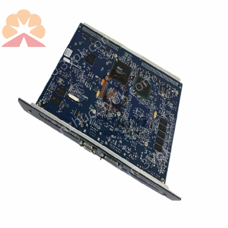
1. Product Overview

2. Key Features
Processor: 600 MHz Pentium‑M microprocessor
Memory: 64 MB battery-backed user RAM + 64 MB non‑volatile user flash memory
Execution Speed: Boolean logic at 0.069 ms / 1000 contacts
I/O Capacity: Up to 32 K discrete bits + 32 K analog words
Ethernet: 2 × 10/100 Mbps auto‑sensing RJ45 ports (half/full duplex)
Serial Ports: 3 isolated ports (RS‑232, RS‑485, RS‑232 station manager)
Protocols:
Ethernet: SRTP, Modbus TCP Server/Client, EGD
Serial: Modbus RTU Slave, SNP, Serial I/O
Programming: IEC 61131‑3 (Ladder, Structured Text, FBD, C)
Real‑Time Clock (RTC): Battery‑backed (CR2032, 3‑year life)
** certifications**: UL 61010‑1, CE, RoHS 2.0
3. Technical Specifications
3.1 Processing & Memory
| Parameter | Value |
|---|---|
| Processor | 600 MHz Pentium‑M |
| User RAM | 64 MB (battery‑backed) |
| User Flash | 64 MB (non‑volatile) |
| Boolean Speed | 0.069 ms / 1000 instructions |
| Max Program Blocks | 512 (128 KB max per block) |
| Max Symbol Memory | 10 MB |
3.2 I/O Capacity
| Type | Capacity |
|---|---|
| Discrete I/O | 32 K bits (%I/%Q) |
| Analog I/O | 32 K words (%AI/%AQ) |
3.3 Communication Interfaces
| Interface | Details |
|---|---|
| Ethernet (2 ports) | 10/100 Mbps, auto‑negotiate, SRTP/Modbus TCP/EGD |
| RS‑232 | Programming/SNP Slave, isolated |
| RS‑485 | Modbus RTU Slave, isolated |
| Station Manager | RS‑232, local configuration/debug |
3.4 Electrical
| Parameter | Value |
|---|---|
| Backplane Power | +5 VDC @ 3.2 A; ±12 VDC @ 0.003 A |
| Power Consumption | 6 W (idle) – 12 W (full load) |
3.5 Environmental
| Parameter | Value |
|---|---|
| Operating Temp | 0 °C to +60 °C (free cooling) |
| Storage Temp | –40 °C to +85 °C |
| Humidity | 5–95% non‑condensing |
| Altitude | ≤2000 m |
3.6 Mechanical
| Parameter | Value |
|---|---|
| Form Factor | Single‑slot VME64, RX7i rack mount |
| Dimensions (H×W×D) | 200 × 150 × 80 mm |
| Weight | ~1.5 kg |
4. Panel Indicators & Controls
4.1 Front Panel LEDs
| LED | State | Meaning |
|---|---|---|
| PWR (Green) | Solid | Power OK, module active |
| Off | No backplane power | |
| RUN (Green) | Solid | Executing user program |
| Blinking | Initialization/stop mode | |
| Off | Fault or halted | |
| OK (Green) | Solid | Self‑test passed, healthy |
| Blinking | Minor fault/warning | |
| Off | Critical fault | |
| LAN1/LAN2 (Green/Yellow) | Solid | Link active |
| Blinking | Data activity |
4.2 Controls
Reset Button: Momentary press for warm reset; hold 5s for factory reset (use cautiously)
Mode Switch: RUN/STOP (controls program execution)
5. Installation
5.1 Pre‑Installation
Disconnect all power from the RX7i rack and peripherals.
Verify the target slot (CPU slot, typically Slot 1) is empty and backplane is undamaged.
5.2 Rack Installation
Align the module with the RX7i rack’s CPU slot.
Insert firmly until the backplane connector is fully seated.
Secure the module with front‑panel screws (torque to 0.8–1.0 N·m).
Connect Ethernet/serial cables as required.
Restore power; verify PWR and OK LEDs illuminate.
6. Programming & Configuration
6.1 Software
Use Proficy Machine Edition Logic Developer – PLC v4.0+
Supports IEC 61131‑3 languages: Ladder Diagram, Structured Text, Function Block Diagram, and C
6.2 Basic Configuration Steps
Create a new RX7i project in Machine Edition.
Select IC698CPE030 as the CPU type.
Configure memory, I/O, and communication ports.
Write/download user program to CPU flash.
Set Mode Switch to RUN; verify RUN LED is solid.
7. Operation
7.1 Power‑On Sequence
Apply power to the RX7i rack; PWR LED lights.
CPU runs self‑diagnostics (OK LED blinks during test).
On successful test, OK LED solidifies; RUN LED lights (if mode = RUN).
7.2 Normal Operation
Executes user program synchronously with I/O refresh.
Maintains real‑time clock and data logging.
Communicates with HMI, SCADA, and other controllers via Ethernet/serial.
7.3 Fault Handling
Watchdog Timer: 1 ms–60 s (configurable); triggers fault on timeout
ECC Memory: Detects/corrects single‑bit errors
Fault LEDs: OK LED off = critical fault; blinking = warning
8. Maintenance & Troubleshooting
8.1 Preventive Maintenance
Monthly: Inspect LED status; clean vents with low‑pressure air.
Quarterly: Tighten module screws and cable connections.
Annual: Replace RTC battery (CR2032); verify flash memory integrity.
8.2 Troubleshooting
| Symptom | Possible Cause | Solution |
|---|---|---|
| PWR LED Off | No backplane power; faulty PSU | Check IC698PSA100 power supply; reseat module |
| OK LED Blinking | Low battery; minor config error | Replace RTC battery; verify project configuration |
| RUN LED Off | Mode = STOP; program fault | Set mode to RUN; download valid program |
| Ethernet Link Down | Cable fault; incorrect IP | Replace cable; verify IP/subnet settings |
| Serial Comm Fail | Wrong protocol; wiring error | Check protocol (Modbus RTU/SNP); verify TX/RX wiring |
9. Safety Precautions
Electrical Hazard: Backplane voltage can be lethal; disconnect power before servicing.
ESD Protection: Use anti‑static wristband when handling the module to avoid damage.
Temperature: Do not operate outside 0–60 °C; ensure adequate ventilation.
Explosive Atmospheres: Not certified for use in hazardous (explosive) locations.
10. Warranty & Support
Warranty: 12 months from delivery (defects in materials and workmanship).
Support: Contact Emerson Automation Solutions for technical assistance, repairs, or firmware updates.
Get a Quote