IC695CRU320
Description
1. Product Overview

2. Key Features
DeviceNet Master: Manages up to 63 slave nodes (e.g., I/O blocks, drives, sensors)
Baud Rates: 125 kbps, 250 kbps, 500 kbps (standard DeviceNet speeds)
I/O Connections: Supports 126 total I/O connections (2 per slave)
Data Capacity: Up to 255 bytes input / 255 bytes output per slave; 3972 bytes explicit message data
Isolation: 1500 VDC isolation between field network and PLC logic
Service Port: RS-232 DB9 port for firmware updates and diagnostics
Firmware: Field-upgradable via RS-232 port
Compliance: ODVA, UL, CE, RoHS certified
3. Technical Specifications
3.1 Electrical
| Parameter | Value |
|---|---|
| Backplane Power | +5 VDC @ 450 mA (typical) |
| DeviceNet Voltage | 12–24 VDC (positive logic) |
| Isolation | 1500 VDC (field-to-logic) |
3.2 Communication
| Parameter | Value |
|---|---|
| Protocol | DeviceNet (ODVA-compliant) |
| Baud Rates | 125 kbps, 250 kbps, 500 kbps |
| Slave Nodes | Up to 63 |
| I/O Connections | 126 total (2 per slave) |
| Data Size (I/O) | 255 bytes input / 255 bytes output per slave |
| Data Size (Explicit) | 3972 bytes input / 3972 bytes output |
| Connectors | 5-pin DeviceNet (V+, CAN_H, Shield, CAN_L, V–); RS-232 DB9 |
3.3 Environmental
| Parameter | Value |
|---|---|
| Operating Temperature | 0 °C to +60 °C (free cooling) |
| Storage Temperature | –40 °C to +85 °C |
| Humidity | 5–95% non-condensing |
| Altitude | ≤2000 m |
3.4 Mechanical
| Parameter | Value |
|---|---|
| Form Factor | Single-slot Series 90-30 rack mount |
| Dimensions (H×W×D) | 120 × 80 × 30 mm |
| Weight | ~0.45 kg |
| Mounting | Main rack only; any slot except 0 and 1 (not for remote/expansion racks) |
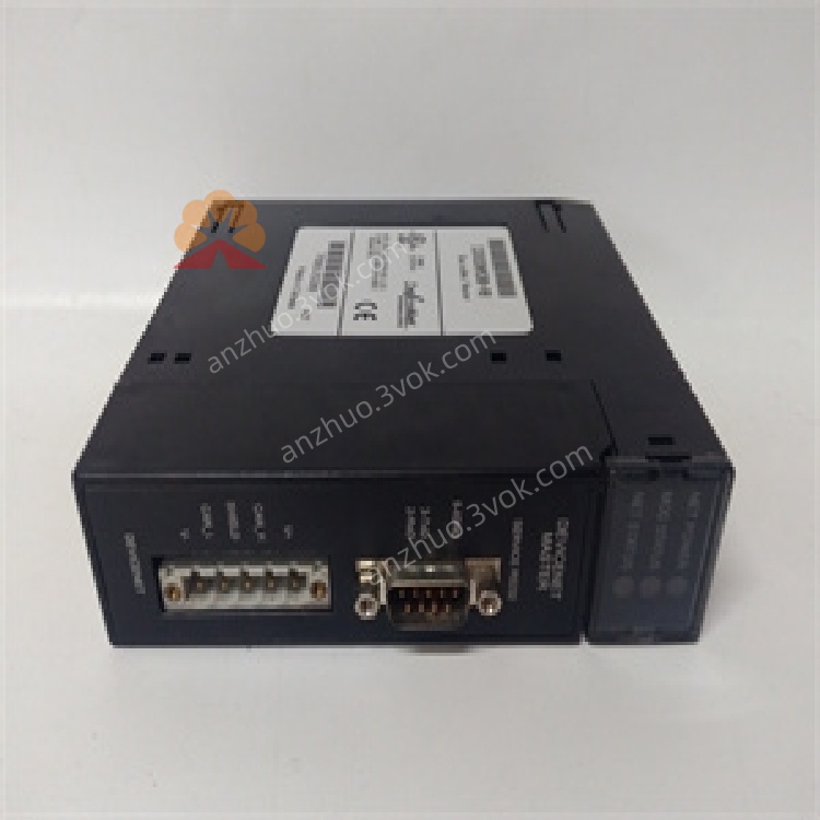
4. Panel Indicators & Connectors
4.1 Front Panel LEDs
| LED | State | Meaning |
|---|---|---|
| PWR (Green) | Solid | Backplane power OK |
| Off | No power or fault | |
| NET OK (Green) | Solid | DeviceNet network operational |
| Blinking | Network activity | |
| Off | No network connection | |
| MODULE OK (Green) | Solid | Module self-test passed |
| Blinking | Firmware update mode | |
| Off | Critical fault | |
| ERROR (Red) | Solid | Network error (e.g., node conflict) |
| Blinking | Minor fault (e.g., slave timeout) | |
| Off | Normal operation |
4.2 Connectors
DeviceNet Port: 5-pin terminal block (V+, CAN_H, Shield, CAN_L, V–)
RS-232 Service Port: DB9 female (for firmware updates and diagnostics)
5. Installation
5.1 Pre-Installation
Disconnect all power from the Series 90-30 rack and DeviceNet network.
Select target slot (main rack only, slots 2+; not for remote racks).
Verify backplane is undamaged and slot is empty.
5.2 Rack Installation
Align module with selected rack slot.
Insert firmly until backplane connector is fully seated.
Secure module with front-panel screws (torque 0.6–0.8 N·m).
Connect DeviceNet cable to 5-pin terminal block (follow polarity: V+, CAN_H, Shield, CAN_L, V–).
Restore power; verify PWR and MODULE OK LEDs illuminate.
5.3 Network Wiring
Topology: Trunk-line with drop lines (max 63 nodes)
Cable: Shielded 5-conductor DeviceNet cable (thick/thin gauge)
Termination: 120 Ω resistors at both ends of trunk line
Grounding: Shield grounded at one end only (to avoid ground loops)
6. Configuration
6.1 Software Requirements
Proficy Machine Edition Logic Developer – PLC v3.0 SP1 Special 2+
EDS Files: Required for slave device configuration (provided by vendor)
6.2 Basic Configuration Steps
In Machine Edition, navigate to I/O Configuration → Communication Modules.
Add IC693DNM200 to the project; assign a rack slot.
Configure DeviceNet Network Settings:
Set baud rate (125/250/500 kbps)
Set master node ID (0–63, unique)
Add slave devices (import EDS files); configure node IDs and I/O data sizes.
Map DeviceNet I/O data to PLC memory (%I, %Q, %AI, %AQ).
Download configuration to PLC; power-cycle module to apply settings.
7. Operation
7.1 Power-On Sequence
Apply power to rack; PWR LED lights.
Module runs self-test (MODULE OK blinks during test).
On successful test, MODULE OK solidifies; NET OK lights if network is connected.
Master initializes communication with slaves; I/O data updates begin.
7.2 Normal Operation
I/O Scanning: Master polls slaves cyclically (configurable rate) for input/output data
Explicit Messaging: Supports on-demand data exchange (e.g., parameter reads/writes)
Slave Monitoring: Tracks slave status; logs timeouts or faults to PLC
7.3 Fault Handling
Network Loss: NET OK off; master retries connection periodically
Slave Timeout: ERROR blinks; PLC logs fault code
Node Conflict: ERROR on; resolve duplicate node IDs
Firmware Fault: MODULE OK off; reflash firmware via RS-232
8. Maintenance & Troubleshooting
8.1 Preventive Maintenance
Monthly: Inspect LED status; clean connectors with lint-free cloth
Quarterly: Tighten module screws and cable connections; check termination resistors
Annual: Update firmware (if available); verify network integrity
8.2 Troubleshooting
| Symptom | Possible Cause | Solution |
|---|---|---|
| PWR LED Off | No backplane power; faulty PSU | Check Series 90-30 power supply; reseat module |
| NET OK LED Off | Cable fault; missing termination | Replace cable; verify 120 Ω resistors at trunk ends |
| ERROR LED On | Duplicate node ID; faulty slave | Check node IDs; replace faulty slave device |
| No I/O Data | Incorrect data mapping; baud rate mismatch | Verify PLC memory mapping; match baud rates across network |
| Firmware Update Failed | Wrong cable; incorrect software | Use null-modem RS-232 cable; update to compatible Machine Edition version |
9. Safety Precautions
Electrical Hazard: Backplane and DeviceNet voltages can be lethal; disconnect power before servicing
ESD Protection: Use anti-static wristband when handling module to avoid damage
Network Isolation: Ensure DeviceNet network is isolated from high-voltage circuits
Termination: Always use 120 Ω termination resistors to prevent signal reflection
Firmware Updates: Follow instructions carefully to avoid bricking the module
10. Warranty & Support
Warranty: 12 months from delivery (defects in materials and workmanship)
Support: Contact Emerson Automation Solutions for technical assistance, repairs, or firmware updates
Get a Quote