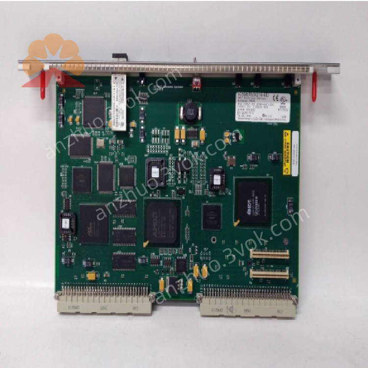
IC698RMX016 VMIVME-5567-100
Description
1. Product Overview

2. Key Features
Reflective Memory Technology: Real-time data mirroring across up to 256 nodes
Fiber Optic Interface: 2 × LC-type fiber ports (62.5/125 μm multimode)
Data Transfer Rate: 2.12 Gbaud (fiber), up to 200 MB/s (payload)
Memory Size: 16 MB shared memory space
Redundancy Support: Dual-module redundancy (primary/backup)
VMEbus Compatibility: VME64x standard, single-slot form factor
Protocols: Reflective Memory Protocol (RMP), supports GE 5565-series devices
Interrupt Support: VME interrupts for event-driven data exchange
Diagnostics: On-board LED indicators, parity error detection
3. Technical Specifications
3.1 Electrical
| Parameter | Value |
|---|---|
| Backplane Power | +5 VDC @ 1.2 A; ±12 VDC @ 0.1 A |
| Power Consumption | 6 W (typical) |
| Isolation | 1500 VDC (fiber-to-backplane) |
3.2 Communication
| Parameter | Value |
|---|---|
| Fiber Ports | 2 × LC (multimode, 62.5 μm core) |
| Fiber Distance | Up to 300 m (62.5 μm multimode) |
| Data Rate | 2.12 Gbaud (fiber), 200 MB/s (max payload) |
| Network Nodes | Up to 256 (compatible with 5565-series) |
| Shared Memory | 16 MB (global address space) |
| Access Time | 200–400 ns |
3.3 Environmental
| Parameter | Value |
|---|---|
| Operating Temperature | 0 °C to +60 °C (free cooling) |
| Storage Temperature | –40 °C to +85 °C |
| Humidity | 5–95% non-condensing |
| Altitude | ≤2000 m |
| Shock/Vibration | IEC 60068-2-6 compliant |
3.4 Mechanical
| Parameter | Value |
|---|---|
| Form Factor | Single-slot VME64x, RX7i rack mount |
| Dimensions (H×W×D) | 170 × 150 × 30 mm |
| Weight | ~1.2 kg |
| Mounting | RX7i main rack (Slot 3/4 recommended) |
4. Panel Indicators & Controls
4.1 Front Panel LEDs
| LED | State | Meaning |
|---|---|---|
| PWR (Green) | Solid | Backplane power OK |
| Off | No power or fault | |
| LINK (Green) | Solid | Fiber link active |
| Blinking | Data activity | |
| Off | No fiber connection | |
| FAULT (Red) | Solid | Parity error / hardware fault |
| Blinking | Network timeout / sync loss | |
| Off | Normal operation |
4.2 Controls
Reset Button: Momentary press to reset module (preserves memory data)
Fiber Ports: 2 × LC connectors (PORT1/PORT2) for network connection
5. Installation
5.1 Pre-Installation
Disconnect all power from the RX7i rack.
Select target slot (Slot 3 or 4 recommended for interrupt priority).
Verify backplane is undamaged and slot is empty.
5.2 Rack Installation
Align module with selected RX7i rack slot.
Insert firmly until backplane connector is fully seated.
Secure module with front-panel screws (torque 0.8–1.0 N·m).
Connect fiber cables to LC ports (PORT1/PORT2).
Restore power; verify PWR LED illuminates.
5.3 Network Wiring
Topology: Daisy-chain or star (using fiber switch)
Cable: 62.5/125 μm multimode fiber, LC connectors
Termination: No external termination required (internal termination)
6. Configuration
6.1 Software Setup
Use Proficy Machine Edition Logic Developer – PLC v4.0+
Configure as IC698RMX016 in RX7i project
6.2 Key Configuration Parameters
Node ID: Unique 0–255 identifier (network-wide)
Memory Offset: 0–16 MB (shared memory address)
Redundancy Mode: Primary/Backup or Dual Primary
Interrupt Enable: VME IRQ 1–7 (event notification)
Parity Check: Enable/disable error detection
6.3 Configuration Steps
In Machine Edition, navigate to I/O Configuration → RMX Module.
Set Node ID and Memory Offset.
Enable Redundancy Mode (if applicable).
Download configuration to CPU.
Power-cycle module to apply settings.
7. Operation
7.1 Power-On Sequence
Apply power to RX7i rack; PWR LED lights.
Module initializes; FAULT LED blinks during self-test.
On successful test, FAULT LED off; LINK LED lights (fiber connected).
CPU configures module; shared memory becomes available.
7.2 Normal Operation
Data Mirroring: Writes to local memory auto-broadcast to all network nodes
Real-Time Sync: Deterministic data update (<1 μs latency)
Redundancy: Backup module auto-takes over if primary fails
Interrupts: Triggers VME interrupt on data update (configurable)
7.3 Fault Handling
Fiber Link Loss: LINK LED off; module retries connection
Parity Error: FAULT LED on; logs error to CPU
Network Timeout: FAULT LED blinks; resets after timeout
Over-temperature: Reduces data rate; shuts down at >70 °C
8. Maintenance & Troubleshooting
8.1 Preventive Maintenance
Monthly: Inspect LED status; clean fiber ports (lint-free cloth)
Quarterly: Tighten module screws; check fiber cable integrity
Annual: Verify memory data integrity; update firmware (if available)
8.2 Troubleshooting
| Symptom | Possible Cause | Solution |
|---|---|---|
| PWR LED Off | No backplane power; faulty PSU | Check RX7i power supply; reseat module |
| LINK LED Off | Fiber cable fault; wrong port | Replace cable; verify PORT1/PORT2 connection |
| FAULT LED On | Parity error; bad memory | Reset module; check configuration |
| Data Not Syncing | Wrong Node ID; memory offset conflict | Verify Node ID; check memory range |
| Interrupts Not Triggering | IRQ disabled; wrong priority | Enable interrupts; check VME IRQ settings |
9. Safety Precautions
Optical Safety: Fiber ports emit laser light; do not look into ports
Electrical Hazard: Backplane voltage can be lethal; disconnect power before servicing
ESD Protection: Use anti-static wristband when handling module
Temperature: Do not operate outside 0–60 °C; ensure adequate ventilation
EMI Compliance: Install in conductive metal enclosure for radiation compliance
10. Warranty & Support
Warranty: 12 months from delivery (defects in materials and workmanship)
Support: Contact Emerson Automation Solutions for technical assistance, repairs, or firmware updates
Get a Quote