UR8FH
Description
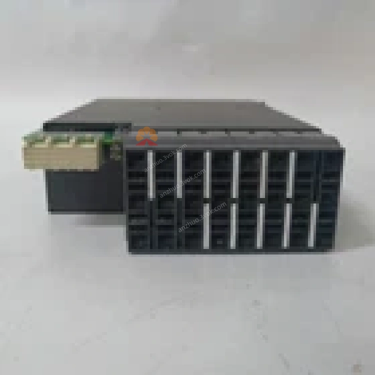
1. Product Overview


Key Features
3 Phase CT Inputs: 1 A / 5 A selectable secondary rating for phase current measurement.
1 Ground CT Input: 1 A / 5 A selectable for residual/ground fault detection.
4 VT Voltage Inputs: For line‑to‑line or line‑to‑neutral voltage monitoring.
High Isolation & Accuracy: Galvanic isolation between CT/VT and relay; class 0.2S accuracy for metering.
Wide Dynamic Range: Supports nominal currents up to 20 × In and voltages up to 2 × Vn without saturation.
Direct Compatibility: Matches UR‑series CPU modules (UR9EH, UR8EH) with “8F” hardware revision.
Hot‑Swappable: Plug‑and‑play replacement without system shutdown.
Industrial Hardening: Conformal coating, extended temperature range, and high immunity to EMI/RFI.
2. Technical Specifications
2.1 General
| Parameter | Specification |
|---|---|
| Manufacturer | GE Multilin (General Electric) |
| Model | UR8FH |
| Type | CT/VT Input Module (UR Series) |
| CT Inputs | 3 phase (1 A / 5 A), 1 ground (1 A / 5 A) |
| VT Inputs | 4 voltage terminals (0–120 V AC nominal) |
| Accuracy | ±0.2% (CT/VT, 20–100% nominal) |
| Isolation | 2 kV AC (CT/VT to relay, 1 min) |
| Power Consumption | < 3 W (from UR backplane) |
| Dimensions (W×H×D) | 22.5 × 110 × 105 mm (0.9 × 4.3 × 4.1 in) |
| Weight | Approx. 250 g (0.55 lb) |
2.2 Environmental
| Parameter | Specification |
|---|---|
| Operating Temperature | −40°C to +85°C (−40°F to 185°F) |
| Storage Temperature | −40°C to +85°C (−40°F to 185°F) |
| Relative Humidity | 5% to 95% (non‑condensing) |
| Vibration | 0.2 mm (5–10 Hz); 1 g (10–200 Hz) |
| Shock | 5 g (10 ms duration) |
| Protection Class | IP20 (front panel) |
2.3 Input Ratings
| Input | Range | Burden |
|---|---|---|
| CT (1 A) | 0–20 A continuous | < 0.1 VA |
| CT (5 A) | 0–100 A continuous | < 0.5 VA |
| VT | 0–120 V AC continuous | < 0.2 VA |
2.4 Compatibility
| Compatible Items | Details |
|---|---|
| Relay Series | GE Universal Relay (UR): G30, G60, L30, D30, UR80, UR100 |
| CPU Modules | UR9EH, UR8EH (matching “8F” hardware revision) |
| Configuration Tools | EnerVista UR Software, Local Keypad/Faceplate |
3. Functional Description
3.1 Signal Acquisition & Conditioning
CT Scaling: Matches 1 A or 5 A secondary CTs via software configuration.
VT Scaling: Adapts to customer VT ratios (e.g., 120 V / 120 V, 600 V / 120 V).
Anti‑Aliasing Filtering: 4th‑order low‑pass filter (cutoff ≈ 2 kHz) for anti‑aliasing.
Overrange Protection: Clamps inputs to prevent damage during fault conditions.
3.2 Data & Fault Processing
Metering Data: Provides high‑accuracy current, voltage, power, energy, and frequency data.
Protection Data: Delivers instantaneous and RMS values for overcurrent, differential, distance, and voltage protection algorithms.
Fault Recording: Captures high‑speed waveform data (up to 64 samples/cycle) for fault analysis.
3.3 Module & System Diagnostics
Module Health: Reports power, communication, and hardware status to the UR CPU.
CT/VT Supervision: Detects open/short circuits, overloads, and ratio mismatches.
Event Logging: Logs module‑level events (e.g., “CT Phase A Overload”) with time stamps.
4. Installation & Wiring
4.1 Module Installation
Power Off: De‑energize the UR relay and isolate all AC/DC power sources.
Slot Access: Open the UR front panel to access the I/O module slots.
Insert Module: Align the UR8FH with the slot guides; push firmly until the module seats into the backplane connector.
Secure: Tighten the two front‑panel captive screws (torque to 0.8–1.0 N·m).
Power On: Restore power; verify the OK LED (green) on the CPU is steady.
4.2 Wiring Guidelines
CT Wiring (Phase & Ground)
Terminals: Connect phase CTs to Ia, Ib, Ic; ground CT to In.
Polarity: Match CT H1/X1 to relay + terminal; H2/X2 to − terminal.
Secondary Rating: Select 1 A or 5 A in EnerVista (must match CT nameplate).
Shorting: Short CT secondary terminals before wiring; open only after all connections are secure.
VT Wiring
Terminals: Connect VT phases to Va, Vb, Vc; neutral to Vn (if used).
Voltage: Do not exceed 120 V AC nominal (2 × Vn max).
Grounding: Ground VT secondary neutral at one point only (relay or substation ground).
4.3 Termination & Shielding
Shielded Cable: Use twisted‑pair, shielded cable for all CT/VT wiring.
Shield Grounding: Connect shield to substation ground at the relay end only; isolate at the transformer end.
No Termination: CT/VT inputs do not require termination resistors.
5. Configuration
5.1 Software Requirements
EnerVista UR Software: v7.0 or later (full configuration, monitoring, and firmware upgrades).
Local Keypad/Faceplate: For basic status checks and parameter adjustments.
5.2 Configuration Steps
Connect: Use Ethernet or RS‑485 to connect a PC (with EnerVista) to the UR relay.
Detect Module: The software automatically detects the UR8FH and reads its factory calibration data.
Set CT Parameters:
Secondary Rating: 1 A or 5 A (match CTs).
CT Ratio: Primary/secondary (e.g., 2000:5).
Connection: 3‑phase 3‑wire or 4‑wire.
Set VT Parameters:
VT Ratio: Primary/secondary (e.g., 6000:120).
Connection: Wye (4‑wire) or delta (3‑wire).
Enable Supervision: Activate CT open/short and VT fuse loss detection (adjust thresholds as needed).
Download: Save and download the configuration to the UR relay; the UR8FH initializes and starts data acquisition.
Verify: Check metered values (current, voltage) in EnerVista; confirm no “Module Mismatch” or “CT/VT Fault” alarms.
6. LED Indicators (via CPU Faceplate)
| LED | Color | Status | Description |
|---|---|---|---|
| OK (CPU) | Green | Steady On | UR8FH powered, communicating, and no faults |
| OK (CPU) | Green | Blinking | UR8FH initializing or minor fault (e.g., CT overload) |
| OK (CPU) | Off | — | UR8FH not detected, power loss, or critical failure |
| ALARM (CPU) | Red | On | CT/VT supervision fault (open/short, ratio mismatch) |
7. Maintenance & Troubleshooting
7.1 Routine Maintenance
Visual Inspection: Check for loose wiring, damaged terminals, or bent module pins.
LED & Alarm Check: Verify steady green OK LED; clear any ALARM conditions.
Calibration Check: Compare metered values with a reference meter (annual calibration recommended).
Cleaning: Power off; blow compressed air through ventilation slots to remove dust.
Backup: Save configuration and event logs via EnerVista.
7.2 Common Issues & Solutions
| Symptom | Possible Cause | Solution |
|---|---|---|
| CPU “Module Mismatch” | UR8FH revision incompatible with CPU | Verify “8F” revision; replace with matching module |
| CT Open Circuit Alarm | Loose CT wire, broken conductor, or open CT | Inspect wiring; tighten connections; test CT continuity |
| Inaccurate Current/Voltage | Incorrect CT/VT ratio, polarity reversal, or overload | Check ratio settings; reverse polarity; reduce load to <20 × In |
| No VT Voltage Reading | Blown VT fuse, loose VT wire, or incorrect connection | Replace fuse; inspect wiring; verify wye/delta configuration |
| Module Not Detected | Poor backplane contact or faulty UR8FH | Reinsert module; tighten screws; replace if faulty |
8. Ordering Information
Model: UR8FH
Description: GE Multilin UR Series CT/VT Input Module (8F Revision)
Accessories:
UR‑CBL‑CTVT: Shielded twisted‑pair cable (500 ft)
UR‑ACC‑TERM: CT shorting terminal kit
UR‑ACC‑SHLD: Shield grounding kit
9. Compliance & Certifications
CE: Compliant with EU EMC (2014/30/EU) and LVD (2014/35/EU) Directives.
UL: UL 508 Listed for Industrial Control Equipment.
RoHS: Compliant with Restriction of Hazardous Substances (2011/65/EU).
IEC: Compliant with IEC 60255‑11 (CT/VT Inputs), IEC 61000‑6‑2/4 (EMC).
Get a Quote