IC698PSA100
Description
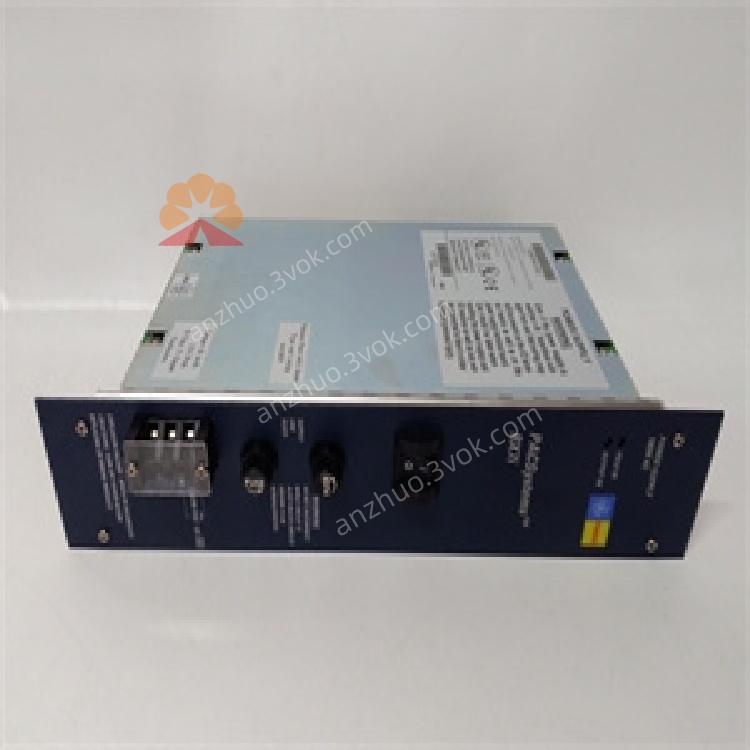
IC698PSA100
100W Universal AC/DC Power Supply Module
User Manual (English)
1. Product Overview

2. Key Features
Universal Input: 85–264 VAC (47–63 Hz) or 100–150 VDC
Total Output Power: 100 W (natural convection cooling, 0–60 °C)
Outputs:
+5.1 VDC: 0–20 A
+12 VDC: 0–2 A
–12 VDC: 0–1 A
Ride-through: 15 ms (survives one AC line cycle loss)
Holdup Time: 5 ms (DC output drop-out hold-up)
Protection: Overvoltage, overcurrent, short-circuit, overtemperature
Isolation: 1500 VDC (input-to-output)
Power Factor: 0.99 min. (AC operation)
Front Panel: ON/OFF switch (logic-level, no AC line disconnect) + LED status indicators
3. Technical Specifications
3.1 Electrical
| Parameter | Value |
|---|---|
| Input Voltage (AC) | 85–264 VAC, 47–63 Hz |
| Input Voltage (DC) | 100–150 VDC |
| Input Power | 125 W (typ.), 150 W (max.) |
| Inrush Current | 15 A max. (cold start, 115 VAC) |
| Output Voltages | +5.1 VDC, +12 VDC, –12 VDC |
| Output Currents | +5.1 VDC: 20 A; +12 VDC: 2 A; –12 VDC: 1 A |
| Total Output Power | 100 W max. |
| Efficiency | >85% (full load, 230 VAC) |
| Isolation | 1500 VDC (input-output) |
| Ride-through | 15 ms |
| Holdup Time | 5 ms |
3.2 Environmental
| Parameter | Value |
|---|---|
| Operating Temperature | 0 °C to +60 °C |
| Storage Temperature | –40 °C to +85 °C |
| Humidity | 5–95% non-condensing |
| MTBF | ≥ 100,000 hours (25 °C, full load) |
| Protection Class | IP30 (enclosed cabinet use) |
3.3 Mechanical
| Parameter | Value |
|---|---|
| Form Factor | PICMG 2.11 standard, slide-in VME64 |
| Dimensions (H×W×D) | 170 × 150 × 30 mm |
| Weight | ~1.2 kg |
| Mounting | RX7i main rack Slot 0 (leftmost) |
4. Panel Controls & Indicators
4.1 Front Panel
ON/OFF Switch: Logic-level switch; enables/disables DC outputs (does not cut AC input)
LED Indicators:
LED State Meaning PWR (Green) Solid ON Input power OK, DC outputs active OFF No input power or outputs disabled FAULT (Red) Solid ON Overvoltage/overcurrent/overtemperature Blinking Minor fault or shutdown imminent OFF Normal operation
5. Installation
5.1 Pre-Installation
Disconnect all power from the RX7i rack and connected devices.
Verify the rack is properly grounded and Slot 0 is empty.
5.2 Rack Installation
Align the module with Slot 0 (leftmost) of the RX7i backplane.
Insert firmly until the connector is fully seated.
Secure the module with front-panel screws.
Connect AC or DC input power to the module’s terminal block.
Set the front-panel switch to ON to enable backplane power.
5.3 Wiring
AC Input: Connect L (Line), N (Neutral), PE (Protective Earth)
DC Input: Connect +100–150 VDC and 0 VDC; observe polarity
Grounding: Connect PE to protective earth for safety and noise reduction
6. Operation
6.1 Power-On Sequence
Apply AC/DC input power to the module.
Set front-panel switch to ON.
Check PWR LED is solid green; FAULT LED is off.
The backplane receives +5 VDC, +12 VDC, –12 VDC; CPUs and I/O modules power up.
6.2 Normal Operation
Delivers stable DC power to all rack modules.
Maintains regulation under varying loads (0–100 W).
Automatically recovers from minor transient faults.
6.3 Fault Response
Overvoltage: Shuts down outputs; FAULT LED ON
Overcurrent/Short-Circuit: Limits current; shuts down if persistent
Overtemperature: Reduces power; shuts down at >65 °C
7. Maintenance & Troubleshooting
7.1 Preventive Maintenance
Monthly: Inspect LED status, clean vents (low-pressure air), check connections.
Quarterly: Verify input voltage and load current; tighten terminals.
Annual: Inspect for corrosion; test isolation resistance.
7.2 Troubleshooting
| Symptom | Possible Cause | Solution |
|---|---|---|
| PWR LED OFF | No input power / Switch OFF / Blown fuse | Check AC/DC supply; set switch to ON; replace fuse |
| FAULT LED ON | Overload / Short circuit / Over-temperature | Reduce load; check backplane wiring; improve ventilation |
| Output Voltage Low | Overload / Input voltage out of range | Reduce load; verify AC/DC input is within specs |
| Intermittent Power | Loose connections / Poor grounding | Re-seat module; tighten wiring; improve PE connection |
8. Safety Precautions
Lethal voltages present inside when input power is applied; disconnect power before servicing.
Do not operate outside 0–60 °C; avoid blocking ventilation slots.
Ensure reliable protective earth (PE) connection to reduce shock and fire risk.
Do not use in explosive or corrosive atmospheres.
9. Warranty & Support
Warranty: 12 months from delivery (defects in materials and workmanship).
Support: Contact Emerson Automation Solutions for technical assistance, repairs, or firmware updates.
Get a Quote