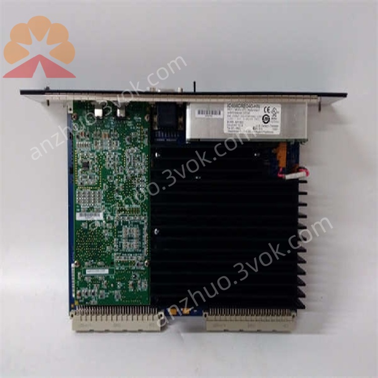
IC698CRE040-HN
Description
1. Product Overview

2. Key Features
Processor: Intel Pentium‑M @ 1.8 GHz
Memory:
64 MB battery-backed RAM (user program/data)
64 MB non‑volatile flash memory (program storage, configuration)
Execution Speed: 0.024 ms / 1000 Boolean contacts/coils
Communication Ports:
2 × Ethernet (RJ45, 10/100 Mbps, auto‑negotiation)
2 × Serial (RS‑232 / RS‑485, software‑selectable)
1 × Station Manager Port (local configuration/firmware updates)
Redundancy: Hot Standby (HSB) support (requires IC698RMX016 Redundancy Memory Xchange module)
Protocols: Modbus/TCP (Server/Client), EGD, SRTP, Modbus RTU, SNP, Serial I/O, SNTP
Programming Languages: Ladder Diagram (LD), Structured Text (ST), Function Block Diagram (FBD), C
Max Program Size: 512 program blocks, 128 KB per block
Data Monitoring: Up to 16 combined web server/FTP connections
3. Specifications
3.1 Electrical
| Parameter | Value |
|---|---|
| Power Consumption | +5 VDC: 6.8 A (nominal) |
| +12 VDC: 0.003 A (nominal) | |
| –12 VDC: 0.003 A (nominal) | |
| Real-Time Clock Accuracy | ±0.01% max; ±2 seconds/day max drift |
3.2 Environmental
| Parameter | Value |
|---|---|
| Operating Temperature | 0 °C to +55 °C |
| Storage Temperature | –20 °C to +85 °C |
| Humidity | 5–95% non‑condensing |
| MTBF | 200,000 hours (typical) |
3.3 Mechanical
| Parameter | Value |
|---|---|
| Form Factor | VME64 standard |
| Dimensions | 170 × 150 × 30 mm |
| Weight | ~1.2 kg |
| Mounting | Slide‑in to RX7i rack CPU slot |
4. Installation
4.1 Rack Installation
Power off the RX7i rack and all connected devices.
Insert the IC698CRE040-HN into the CPU slot (typically the leftmost slot) of the RX7i rack.
Push firmly until the module fully seats into the VME64 backplane connector.
Secure the module with the front‑panel screws.
4.2 Redundancy Setup (Hot Standby)
Install two IC698CRE040‑HN CPUs in separate RX7i racks (primary and secondary).
Install one IC698RMX016 Redundancy Memory Xchange module in each rack.
Connect the RMX modules via a fiber or copper redundancy link.
Configure redundancy parameters (e.g., IP addresses, sync settings) in Proficy Machine Edition / Logic Developer software.
Verify redundancy operation: The secondary CPU automatically synchronizes with the primary and takes over within <100 ms if the primary fails.
5. Communication Interfaces
5.1 Ethernet Ports (ETH1, ETH2)
Speed: 10/100 Mbps, full‑duplex, auto‑negotiation
Protocols: Modbus/TCP, EGD, SRTP, TCP/IP, SNTP (time synchronization)
Functions: Programming, HMI/SCADA communication, data exchange, web server/FTP access
Redundant IP: Configurable for EGD data exchange (supports network redundancy)
5.2 Serial Ports (COM1, COM2)
Modes: RS‑232 (point‑to‑point) or RS‑485 (multi‑drop), software‑selectable
Protocols: Modbus RTU (Slave), SNP, Serial I/O
Use Cases: Legacy device communication, programming, HMI connection
5.3 Station Manager Port
Function: Local configuration, firmware updates, diagnostics, and troubleshooting
6. Operation
6.1 Power‑On
Apply power to the RX7i rack.
Check front‑panel LEDs:
RUN (Green): Solid = CPU executing program; Blinking = Startup/firmware update
FAULT (Red): Off = Normal; Solid = Critical fault; Blinking = Minor fault/warning
ETH1/ETH2 (Yellow/Green): Blinking = Network activity
6.2 Normal Operation
Executes user program and updates I/O every scan cycle.
Maintains real‑time clock and battery‑backed memory (preserves data during power loss).
Communicates with HMIs, SCADA, and other controllers via Ethernet/serial.
In redundant systems, the secondary CPU continuously synchronizes with the primary.
7. Programming
7.1 Software
Use Proficy Machine Edition or Logic Developer (Emerson Automation Solutions).
7.2 Supported Languages
Ladder Diagram (LD): Standard for relay‑logic applications
Structured Text (ST): High‑level, Pascal‑like language
Function Block Diagram (FBD): Graphical, block‑based programming
C Language: For complex algorithms and custom functions
7.3 Program Structure
Program Blocks: Up to 512 blocks (max 128 KB per block)
Memory Reference: %W reference table for bulk memory access
Symbolic Variables: Auto‑located, use user memory dynamically
8. Protection & Diagnostics
8.1 Error Conditions
CPU Fault: Hardware/software error (check firmware, program, or backplane connection)
I/O Fault: Missing/faulty I/O module (inspect backplane, wiring, or module)
Communication Fault: Network/serial link failure (check cables, settings, or devices)
Redundancy Fault: Sync failure between primary/secondary (check RMX module, link, or config)
8.2 LED Indicators
| LED | State | Meaning |
|---|---|---|
| RUN | Solid Green | Normal operation |
| Blinking Green | Startup / firmware update | |
| FAULT | Solid Red | Critical fault (CPU/I/O/Communication) |
| Blinking Red | Minor fault / warning | |
| ETH1/ETH2 | Blinking | Network activity (data transmission/reception) |
9. Maintenance
9.1 Regular Checks
Monthly: Verify LED status, clean dust from vents (use low‑pressure air), check cable connections.
Quarterly: Update firmware (if available), verify redundancy synchronization.
Annually: Replace battery (every 3–5 years) to preserve memory during power loss.
9.2 Troubleshooting
| Symptom | Possible Cause | Solution |
|---|---|---|
| No RUN LED | No rack power / CPU not seated | Check power supply; re‑seat CPU |
| FAULT LED On | Program error / I/O fault / Redundancy sync failure | Download blank program; check I/O modules; verify RMX connection |
| Ethernet Link Down | Cable fault / Switch port issue | Replace cable; check switch port settings |
| Redundancy Switchover Failure | RMX module fault / Link issue / Config error | Check RMX module; test redundancy link; verify software config |
| Battery Low Warning | Weak battery | Replace battery; ensure proper connection |
10. Warranty & Support
Warranty: 1‑year manufacturer’s warranty against defects in materials and workmanship.
Support: Contact Emerson Automation Solutions for technical assistance, firmware updates, or repair services.
11. Safety Precautions
Disconnect power before installation, wiring, or maintenance to avoid electric shock.
Do not operate outside the 0 °C to +55 °C temperature range to prevent overheating.
Ensure proper grounding of the rack and modules to reduce electrical noise and shock hazards.
Keep ventilation vents clear of dust and debris to maintain airflow.
In redundant systems, verify switchover operation during scheduled maintenance to ensure high availability.
Get a Quote