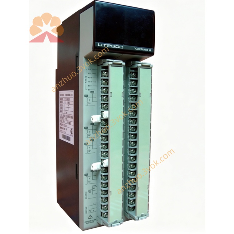
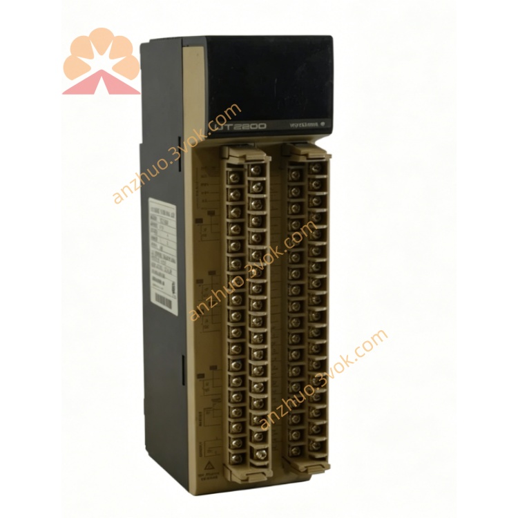
UT2800
Description
FEATURES
Universal Input: Supports DC voltage/current, thermocouple (B, K, R, S, N, T, E, J), and RTD (PT100, JPT100).
High-Contrast LED Display: Dual 4-digit displays for PV (Process Value) and SP (Setpoint); 11-segment bar graph for trend visualization.
Multiple Alarm Functions: High/low limit, deviation, and rate-of-change alarms; relay output (250 VAC, 3 A resistive).
Universal Power Supply: 100–240 VAC, 50/60 Hz; optional 24 VDC power.
Compact 1/4 DIN Size: Panel-mountable; depth 100 mm.
Communication Option: RS-485 (Modbus RTU) for data exchange with PCs or PLCs.
Self-Diagnosis: Detects input errors, hardware faults, and displays error codes.
2. SAFETY PRECAUTIONS
Installation: Only qualified personnel should install/wire the unit.
Power: Disconnect power before wiring or maintenance.
Environment: Avoid direct sunlight, vibration, dust, moisture, and corrosive gases. Operating temperature: 0–50°C; humidity: 10–90% RH (non-condensing).
Wiring: Use shielded cables for inputs/communication. Separate signal and power wiring.
Maintenance: Do not open the unit; no user-serviceable parts. Contact Yokogawa service for repairs.
3. UNPACKING AND CHECKING
Verify package contents: UT2800 controller, mounting brackets, terminal screws, user manual.
Check for physical damage (dents, scratches).
Confirm model code on the nameplate matches your order.
4. INSTALLATION
4.1 Panel Mounting
Cut a 92 × 92 mm square hole in the panel (thickness 1–5 mm).
Insert the controller into the hole from the front.
Attach mounting brackets to the rear and tighten screws to secure the unit.
Ensure the front panel is flush with the panel surface.
4.2 Wiring
Terminal Layout (Rear Panel)
1–2: Power (100–240 VAC)
3–4: Alarm relay output (NO/COM)
5–6: RS-485 (A/B)
7–8: Input (+/–)
9: Common (GND)
Wiring Steps
Connect power wires to terminals 1–2.
Connect input sensor (thermocouple/RTD/DC) to terminals 7–8 and 9.
Connect alarm output to external devices (e.g., buzzer, lamp) via terminals 3–4.
Connect RS-485 communication wires (if used) to terminals 5–6.
Tighten all terminal screws securely.
5. OPERATION
5.1 Front Panel
PV Display (Upper): Shows process value (temperature, pressure, etc.).
SP Display (Lower): Shows setpoint or parameter values.
Bar Graph: Indicates PV relative to SP (–100% to +100%).
Keys:
SET: Enter/exit parameter setting mode.
▲/▼: Adjust values or select parameters.
◄: Move cursor left.
ENT: Confirm and save settings.
5.2 Basic Operation
Power On
Apply power; the PV display shows the current process value, and the SP display shows the setpoint.
Setpoint Adjustment
Press SET once; the SP display flashes.
Use ▲/▼ to adjust the setpoint.
Press ENT to save the new setpoint.
Parameter Setting
Press SET for 3 seconds to enter setting mode.
Use ▲/▼ to select a parameter (e.g., input type, alarm value).
Press ENT to enter the parameter.
Use ▲/▼ and ◄ to adjust the value.
Press ENT to save the value.
Press SET for 3 seconds to exit setting mode.
5.3 Input Type Setting
Enter setting mode (press SET for 3 seconds).
Select parameter IN.TYP (Input Type).
Press ENT; use ▲/▼ to select the input type (e.g., K for thermocouple, PT100 for RTD).
Press ENT to save.
5.4 Alarm Setting
Enter setting mode.
Select parameter AL.HI (High Alarm Value).
Press ENT; use ▲/▼ to set the high alarm threshold.
Press ENT to save.
Repeat for AL.LO (Low Alarm Value) if needed.
6. ERROR CODES
ERR 01: Input open (sensor disconnected or broken).
ERR 02: Input overrange (PV exceeds measurement range).
ERR 03: Input underrange (PV below measurement range).
ERR 04: Hardware fault (internal circuit error).
ERR 05: Communication error (RS-485 connection failed).
7. SPECIFICATIONS
Input: Universal (DC: 0–10 V, 4–20 mA; Thermocouple: B/K/R/S/N/T/E/J; RTD: PT100/JPT100).
Measurement Range:
DC: –10 to +10 V, 0–20 mA.
Thermocouple: –200 to +1800°C (depends on type).
RTD: –200 to +650°C.
Accuracy: ±0.1% of span (DC), ±0.15% of span (thermocouple/RTD).
Display: Dual 4-digit LED (PV: red, SP: green); 11-segment bar graph.
Alarm: 1 relay output (NO/COM), 250 VAC, 3 A resistive.
Communication: RS-485 (Modbus RTU), 9600 bps, 8N1.
Power: 100–240 VAC, 50/60 Hz, 10 VA; optional 24 VDC.
Environment: 0–50°C, 10–90% RH (non-condensing).
Dimensions: 96 × 96 × 100 mm (1/4 DIN).
Weight: Approx. 0.5 kg.
8. MAINTENANCE
Cleaning: Wipe the front panel with a soft, dry cloth. Do not use water or harsh chemicals.
Calibration: Calibrate annually using a standard signal source (e.g., precision voltage/current generator, calibrated thermocouple/RTD).
Replacement: If the unit fails or is damaged, replace it with a new UT2800 controller.
9. OPTIONS
RS-485 Communication: Modbus RTU protocol for data exchange with external devices.
24 VDC Power: For low-voltage power supply applications.
Additional Alarms: Up to 3 relay outputs (optional).
Get a Quote