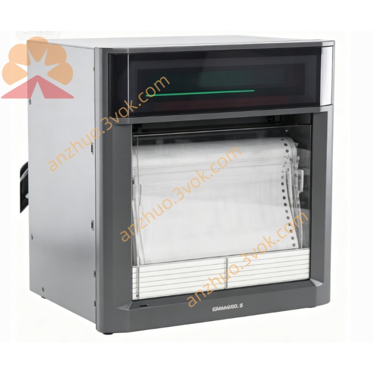
UR1800
Description
1.1 Key Features
Universal Inputs: DC voltage, Thermocouple (TC), RTD, Digital Input (contact).
Large VFD Display: Shows measured data, clock, and bargraph simultaneously.
Multi-Channel Recording: Up to 4 channels (pen model).
Universal Power Supply: 90–250 VAC, 50/60 Hz (except /P1 model).
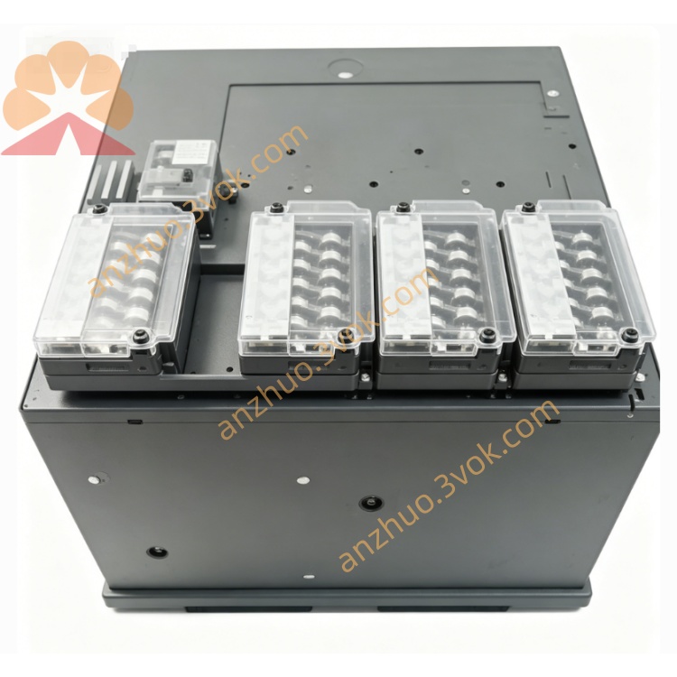
High Reliability: Contact-free potentiometer, brushless-DC motor.
Easy Maintenance: Modular design, few wearing parts.
Options: RS-422-A interface, IC memory card, remote control.
1.2 Function Summary
Recording: Trend, Zone, Partial, POC (Pen Offset Compensation).
Printout: Channel, List, Manual, Alarm, Periodic, Message.
Alarms: High/Low limit, High/Low difference, Rate-of-change.
Calculations: Difference, Linear scaling, Square root, MATH (optional).
2. BEFORE OPERATION
2.1 Handling Precautions
Cleaning: Use a soft, dry cloth. Avoid benzene, thinner, or harsh chemicals.
Static Electricity: Keep static-charged objects away from signal terminals.
Insecticides: Do not expose front door/panel to volatile sprays.
Malfunction: If unusual sounds/smoke occur, disconnect power immediately.
2.2 Unpacking
Check all items against the packing list.
Verify model code on the nameplate.
3. INSTALLATION
3.1 Mounting
Panel Mount Only: Designed for installation in control panels.
Panel Thickness: 2–26 mm.
Cutout Dimensions: Refer to dimensional drawings.
3.2 Wiring
Power: Connect to 90–250 VAC, 50/60 Hz.
Inputs: Wire TC/RTD/DC signals to input terminals.
Alarm Output: Connect relay contacts to external devices.
Remote Control: Wire to CONT 1–5 terminals (optional).
4. OPERATION
4.1 Front Panel Keys
MENU: Enter SET mode (press 3 seconds).
ESC: Return to previous menu.
UP/DOWN: Select menu items/values.
RIGHT: Move cursor during data entry.
ENT: Confirm selection/store settings.
4.2 Display Modes
AUTO: Cycles through all channels.
MAN: Displays a single selected channel.
CLK: Shows date/time.
Bargraph: Left-referenced (%) or Center-zero.
4.3 Basic Operations
Start/Stop Recording: Press REC key.
Load Chart Paper:
Open front door.
Insert chart paper into top hopper.
Engage sprocket teeth with paper perforations.
Close guides and door.
Replace Pens/Ribbon: Open door, remove cassette, replace components.
5. SETTINGS
5.1 Mode Overview
Operation Mode: Normal measurement/recording.
SET Mode: Basic settings (range, alarm, clock).
SET UP Mode: Initial settings (bargraph, temp unit).
5.2 Entering SET Mode
Press MENU for 3 seconds.
Select setting with UP/DOWN → press ENT.
Adjust value with UP/DOWN/RIGHT → press ENT.
Press MENU for 3 seconds to exit.
5.3 Common Settings
Input Range: Set for each channel (mV, V, TC, RTD).
Alarms: Set level, hysteresis, relay assignment.
Clock: Set date (YY/MM/DD) and time (HH:MM:SS).
Chart Speed: Select 5–1500 mm/h.
5.4 Entering SET UP Mode
Power on while holding ENT until “SET UP” appears.
Follow menu prompts → store settings before exiting.
6. MAINTENANCE
Clean Front Door: Monthly with soft cloth.
Replace Battery: Every 5 years (data backup).
Calibration: Annual calibration with standard sources.
Error Codes:
ERROR 011: Chart paper exhausted.
ERROR 040: Invalid reference channel.
ROM/RAM ERROR: System fault (contact service).
7. SPECIFICATIONS
Channels: 1–4 (pen), 6–24 (dot).
Input Ranges:
DC Voltage: 20 mV–20 V.
TC: B, K, R, S, N, T, E, J, L.
RTD: PT100, JPT100.
Accuracy: ±0.1% of span (DC), ±0.15% (TC/RTD).
Power Consumption: 30 VA (4-pen model).
8. OPTIONS
RS-422-A Interface: PC communication.
IC Memory Card: Data/setting storage.
Remote Control: External start/stop, printout.
Alarm Relay Outputs: 4–24 relays.
Get a Quote