SCM4.1
Description
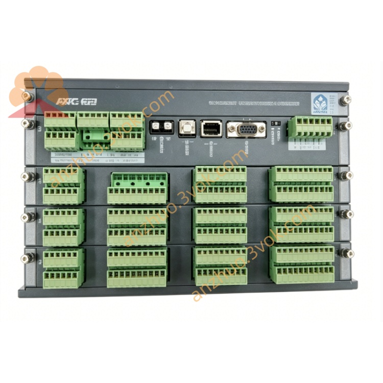
1. Product Overview
2. Main Features
Advanced Synchronization: Programmable Δfrequency, Δvoltage, and Δangle thresholds with adaptive logic for fast, safe generator-to-busbar connection.
High-Precision Measurement: Real-time monitoring of 3-phase generator/busbar voltage, current, frequency, power factor, active/reactive power, and harmonics.
Integrated Protection Suite: Overcurrent (I>), short-circuit (I>>), reverse power (–P>), overpower (P>), over/undervoltage, over/underfrequency, and earth fault protection.
Dual-Loop Regulation: Automatic voltage/reactive power (VAr) control and frequency/active power (kW) control with adjustable PID parameters.
Flexible Communication: Modbus TCP/RTU, CANopen, and Ethernet protocols for seamless data exchange with PLCs, SCADA, and remote monitoring systems.
Marine & Industrial Grade: Rugged design for harsh environments; wide-temperature operation, EMC compliance, and vibration resistance.
LCD Display & Keypad: Built-in backlit LCD for real-time data visualization and local parameter configuration.
Rack Mount Design: Standard 19-inch rack or DIN rail installation for easy cabinet integration.
Fault Data Logging: Non-volatile memory stores up to 100 fault events with timestamps for post-fault analysis.
3. Technical Specifications
3.1 Power Supply
Rated Voltage: 24 VDC (18–30 VDC operating range)
Optional: 110/220 VAC (50/60 Hz)
Power Consumption: ≤15 W
Isolation: 2000 VAC between power and measurement circuits
3.2 Measurement Inputs
Generator Voltage: 0–690 VAC (PT selectable: 100/110/400/690 V)
Generator Current: CT secondary 1A or 5A (selectable via jumper)
Busbar Voltage: 0–690 VAC (PT selectable, same as generator)
Frequency: 45–65 Hz (50/60 Hz compatible)
Accuracy: Class 0.2 (voltage/current); Class 0.5 (power/frequency)
Sampling Rate: 1 kHz per channel (simultaneous sampling)
Harmonic Measurement: Up to 15th harmonic (THD monitoring)
3.3 Synchronization Parameters
ΔFrequency Range: ±0.05–±1.0 Hz (adjustable, default ±0.2 Hz)
ΔVoltage Range: ±1–±10% of rated voltage (adjustable, default ±5%)
ΔAngle Range: 0–30° (adjustable, default 10°)
Synchronization Time: ≤8 seconds (typical, adaptive to conditions)
Mode: Dynamic (auto-adaptive) / static synchronization (selectable)
3.4 Protection Functions (Adjustable Thresholds)
Overcurrent (I>): 100–200% of rated current (1–30 s delay)
Short-Circuit (I>>): 200–500% of rated current (instantaneous, <50 ms)
Reverse Power (–P>): 2–20% of rated active power (1–10 s delay)
Overpower (P>): 100–150% of rated active power (5–60 s delay)
Overvoltage (V>): 105–120% of rated voltage (1–10 s delay)
Undervoltage (V<): 80–95% of rated voltage (1–10 s delay)
Overfrequency (f>): 51–55 Hz (50 Hz system) / 61–65 Hz (60 Hz system)
Underfrequency (f<): 45–49 Hz (50 Hz system) / 55–59 Hz (60 Hz system)
Earth Fault: 5–20% of rated current (1–5 s delay)
3.5 Communication Interfaces
Ethernet: Modbus TCP (10/100 Mbps, RJ45)
Serial: RS485 (Modbus RTU, 9.6 kbps–1 Mbps)
Fieldbus: CANopen (250 kbps–1 Mbps)
Protocol Support: Modbus RTU/TCP, CANopen, DNP3 (optional)
3.6 Environmental Conditions
Operating Temperature: -25°C to +70°C
Storage Temperature: -40°C to +85°C
Relative Humidity: 5–95% RH, non-condensing
Vibration: 5–150 Hz, 0.1 mm amplitude (industrial/marine standard)
Protection Class: IP20 (terminals); IP40 (housing)
3.7 Mechanical Parameters
Mounting: 19-inch rack (3U: 130 mm × 90 mm × 45 mm) or standard 35 mm DIN rail
Housing: Flame-retardant engineering plastic
Weight: ~1.2 kg
4. Application Scope
Generator Parallel Operation: Automatic synchronization and load sharing for diesel/gas generators in marine and industrial power plants.
Marine Switchboards: Main/auxiliary generator control and protection in vessel power systems (compliant with SOLAS).
Industrial Standby Power: Backup generator control for factories, data centers, hospitals, and critical infrastructure.
Onshore Distributed Power Stations: Isolated grid generator control, synchronization, and fault monitoring.
Hybrid Energy Systems: Generator integration with solar/wind power for grid stability and backup power.
5. Installation and Wiring
5.1 Installation Requirements
Mount on a 19-inch rack or standard 35 mm DIN rail inside a control cabinet.
Maintain ≥20 mm clearance around the module for heat dissipation.
Install away from frequency converters, large contactors, and high-power electromagnetic devices to minimize interference.
Use anti-static precautions during installation to avoid damage to internal components.
Do not install in corrosive, dusty, dripping, or condensing environments.
5.2 Wiring Rules
Perform all wiring with the power off; only qualified electrical personnel should install or maintain the module.
Measurement wiring (voltage/current): 1.5–2.5 mm² shielded copper wire; separate from high-voltage cables.
Power wiring: 1.0–1.5 mm² copper wire; use twisted pair for 24 VDC.
Communication wiring: Twisted pair (CAT5e for Ethernet; 0.8–1.0 mm² for RS485/CAN).
Tighten terminal screws to 0.8–1.0 Nm to avoid loose connections and overheating.
Never open CT secondary circuits during operation—this induces lethal high voltage.
5.3 Terminal Definition
Power: +24 VDC, 0 VDC, PE (protective earth)
Generator Voltage: G_L1, G_L2, G_L3, G_N
Generator Current: CT_L1, CT_L2, CT_L3, CT_Common
Busbar Voltage: B_L1, B_L2, B_L3, B_N
Breaker Control: BRK_ON, BRK_OFF, BRK_STATUS (NO/COM/NC)
Relay Outputs: ALARM (NO/COM/NC), TRIP (NO/COM/NC), AUX (NO/COM/NC)
Communication: ETH (RJ45), RS485 (A/B), CAN (H/L)
Digital Inputs: START, STOP, RESET, SYNC_ENABLE
5.4 Wiring Notes
Connect the PE terminal securely to the cabinet ground for safety and EMC protection.
CT circuits must be connected firmly; open CT terminals during operation will induce dangerous high voltage.
Do not apply voltage exceeding 690 VAC to voltage input terminals.
Relay trip outputs shall be matched with breaker coil rated capacity (250 VAC 8A / 24 VDC 8A).
After wiring, double-check all connections to prevent miswiring or reverse polarity.
6. Operation and Configuration
6.1 Indicator & Display Description
PWR: Steady on = power normal; Off = no power or fault.
RUN: Flashing = normal operation; Steady on = fault.
SYNC: Flashing = synchronization in progress; Steady on = synchronized.
COM: Flashing = communication active; Off = no communication.
ALARM: On = alarm triggered; Flashing = latched alarm.
TRIP: On = trip output activated (breaker open).
LCD Display: Real-time voltage, current, frequency, power, and fault messages; backlit for low-light visibility.
6.2 Parameter Configuration (Local/Remote)
- Local Configuration (LCD/Keypad):
Navigate menus using arrow keys; select/confirm with ENTER.
Set PT/CT ratios, rated voltage/frequency, and synchronization thresholds.
Configure protection thresholds, time delays, and regulation PID parameters.
Set communication parameters (IP address, baud rate, protocol).
Save settings to non-volatile memory.
- Remote Configuration (Software):
Connect module to PC via Ethernet/RS485.
Install DEIF Utility Software (compatible with Windows 10/11).
Detect module, configure parameters, and download settings.
Monitor real-time data and view fault logs remotely.
6.3 Normal Operation
7. Safety Precautions
High voltage exists on voltage/current input terminals; wiring and maintenance must be done in power-off state.
Never open CT secondary circuits during operation—this induces lethal high voltage.
Do not disassemble the module without authorization; this voids the warranty and may cause electric shock.
Do not operate beyond the specified voltage, temperature, or vibration limits.
After protection tripping, eliminate the fault and reset the module before re-closing the generator breaker.
Keep the module away from water, moisture, and corrosive substances.
8. Maintenance
Monthly: Check terminal tightness, wire condition, and LED/LCD status.
Quarterly: Clean dust from the surface with a dry soft cloth; do not use liquid cleaners.
Annually: Verify measurement accuracy, synchronization performance, and protection threshold calibration.
As Needed: Update firmware via DEIF Utility Software to add features or fix bugs.
Replacement: If the module fails or is damaged, replace it with a new unit and reload the configuration.
9. Troubleshooting
PWR Off: No 24 VDC power, reverse wiring, or internal fuse blown.
RUN Fault: Self-test failure, configuration error, or hardware fault.
SYNC Failure: Incorrect Δfrequency/Δvoltage/Δangle settings, wiring error, or generator/busbar parameter mismatch.
Measurement Inaccuracy: PT/CT ratio misconfiguration, wiring error, or signal interference.
False Alarm/Trip: Protection thresholds set too low, electrical interference, or ground loop.
Communication Failure: Incorrect settings, cable fault, or network error.
Fault Log Full: Download and clear fault log via software.
10. Warranty and Disclaimer
Model: SCM4.1 Synchronizing & Measuring Module.
Warranty Period: 24 months from the date of delivery, under normal installation and use.
Warranty Exclusions: Damage from wrong wiring, overvoltage, lightning, water ingress, unauthorized disassembly, or operation beyond environmental specifications.
Modifications: The manufacturer reserves the right to update product specifications and this manual without prior notice.
Liability: The manufacturer shall not be liable for any indirect, incidental, or consequential losses arising from improper installation or use.
Get a Quote