RMC-131D/2
Description
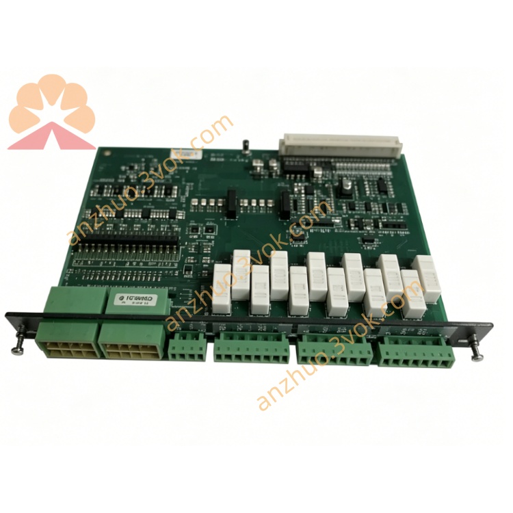
1. Product Overview
1. Product Overview
2. Main Features
Three-Phase Differential Protection: Monitors phase current balance to detect winding short circuits and leakage currents.
Fast Fault Response: <50 ms response time for critical short-circuit protection.
Adjustable Threshold & Delay: Differential current threshold (100–400% of rated) and time delay configurable via front-panel potentiometers.
Dual Relay Outputs: Two sets of parallel relay contacts for alarm and tripping (NO/COM/NC).
LED Status Indicators: Power, differential current, and relay activity LEDs for clear fault diagnosis.
Fault Latch Function: Locks fault status until manual reset to prevent repeated tripping.
Industrial & Marine Grade: Wide-temperature design (-25°C to +70°C), EMC protection, and vibration resistance for harsh environments.
Compact DIN Rail Mount: Standard 35mm DIN rail installation for easy cabinet integration.
Low Power Consumption: ≤2W power draw for energy-efficient operation.
3. Technical Specifications
3.1 Power Supply
Rated Voltage: 24 VDC (18–30 VDC operating range)
Optional: 110 VAC (for specific variants)
Power Consumption: ≤2 W
Isolation: 2000 VAC between power and measurement circuits
3.2 Measurement Input
Current Input: CT secondary 1A or 5A (selectable via model variant)
Measuring Range: 0.4–5 A (CT secondary)
Frequency: 45–65 Hz (compatible with 50/60 Hz systems)
Accuracy: Class 0.5 (RMS measurement); peak sampling for fast response
Overvoltage Category: 600V CAT III
3.3 Protection Parameters
Differential Current Threshold (I>>): 100–400% of rated CT current (adjustable)
Time Delay (T1): 0–5 seconds (adjustable via potentiometer)
Response Time: <50 ms (for faults above threshold)
Reset Mode: Manual reset (fault latch) or automatic reset (configurable)
3.4 Relay Outputs
Contact Rating: 250 VAC 8A / 24 VDC 8A (NO/COM/NC)
Number of Outputs: 2 sets (parallel) for alarm and tripping
Contact Type: Normally Energized (default) or Normally De-energized (configurable)
3.5 Environmental Conditions
Operating Temperature: -25°C to +70°C
Storage Temperature: -40°C to +85°C
Relative Humidity: 5–95% RH, non-condensing
Vibration: 5–150 Hz, 0.1 mm amplitude (industrial/marine standard)
Protection Class: IP40 (housing); IP20 (terminals)
3.6 Mechanical Parameters
Mounting: Standard 35 mm DIN rail or panel mount
Housing: Flame-retardant engineering plastic
Dimensions (W×H×D): 120 mm × 80 mm × 45 mm
Weight: ~480 g
4. Application Scope
Generator Stator Protection: Internal short circuits, winding leakage, and turn-to-turn fault protection for diesel/gas generators.
Marine Power Plants: Main and auxiliary generator protection in vessel switchboards.
Industrial Standby Generators: Backup power systems for factories, data centers, and hospitals.
Onshore Distributed Power Stations: Isolated grid generator protection and fault isolation.
Renewable Energy Hybrid Systems: Generator protection in solar/wind-diesel hybrid power plants.
5. Installation and Wiring
5.1 Installation Requirements
Mount vertically on a standard 35 mm DIN rail inside a control cabinet.
Maintain ≥20 mm clearance around the unit for heat dissipation.
Install away from frequency converters, large contactors, and high-power electromagnetic devices to minimize interference.
Use anti-static precautions during installation to avoid damage to internal components.
Do not install in corrosive, dusty, dripping, or condensing environments.
5.2 Wiring Rules
Perform all wiring with the power off; only qualified electrical personnel should install or maintain the unit.
CT input wiring: 1.5–2.5 mm² copper wire; never open CT terminals when powered on (risk of high voltage).
Power wiring: 1.0–1.5 mm² copper wire; separate from high-voltage cables.
Relay output wiring: 1.5–2.5 mm² copper wire for alarm/trip circuits.
Tighten terminal screws to 0.8–1.0 Nm to avoid loose connections and overheating.
5.3 Terminal Definition
Power: +24 VDC, 0 VDC, PE (protective earth)
CT Inputs: CT1 (L1), CT2 (L2), CT3 (L3), CT Common
Relay Outputs: ALARM (NO/COM/NC), TRIP (NO/COM/NC)
Reset: Manual reset input (dry contact)
5.4 Wiring Notes
Connect the PE terminal securely to the cabinet ground for safety and EMC protection.
CT circuits must be connected firmly; open CT terminals during operation will induce dangerous high voltage.
Do not apply voltage exceeding 600V CAT III to CT input terminals.
Relay trip outputs shall be matched with breaker coil rated capacity.
After wiring, double-check all connections to prevent miswiring or reverse polarity.
6. Operation and Parameter Setting
6.1 Indicator Description
PWR: Steady on = power supply normal; Off = no power or fault.
DIFF CURRENT: On = differential current exceeds threshold; Flashing = fault detected and latched.
RELAY: On = relay activated (alarm/trip); Off = relay de-energized.
6.2 Parameter Configuration
CT Ratio Selection: Confirm CT secondary rating (1A or 5A) and set the unit’s internal jumper accordingly.
Threshold Adjustment: Rotate the "DIFF CURRENT" potentiometer to set the differential current threshold (100–400% of CT rated current).
Time Delay Setting: Rotate the "T1" potentiometer to set the fault delay (0–5 seconds).
Reset Mode: Select manual or automatic reset via internal jumper (default: manual).
Save Settings: Parameters are saved automatically; no additional confirmation required.
6.3 Normal Operation
7. Safety Precautions
High voltage exists on CT input terminals; wiring and maintenance must be done in power-off state.
Never open CT secondary circuits during operation—this induces lethal high voltage.
Do not disassemble the unit without authorization; this voids the warranty and may cause electric shock.
Do not operate beyond the specified voltage, temperature, or vibration limits.
After protection tripping, eliminate the fault manually and reset the unit before re-closing the generator breaker.
Keep the unit away from water, moisture, and corrosive substances.
8. Maintenance
Monthly: Check terminal tightness, wire condition, and LED status.
Quarterly: Clean dust from the surface with a dry soft cloth; do not use liquid cleaners.
Annually: Verify CT input accuracy, protection threshold, and relay contact condition.
As Needed: Test fault response time and reset function to ensure proper operation.
Replacement: If the unit fails or is damaged, replace it with a new unit and reconfigure parameters.
9. Troubleshooting
PWR Off: No 24 VDC power, reverse wiring, or internal fuse blown.
DIFF CURRENT False Alarm: Threshold set too low, CT wiring error, or external interference.
No Protection Action: Threshold set too high, time delay too long, or CT circuit open.
Relay No Output: Relay contact ablation, wiring error, or load overload.
Fault Cannot Be Reset: Fault not eliminated, reset circuit error, or latch circuit abnormal.
10. Warranty and Disclaimer
Model: RMC-131D/2 Differential Current Relay.
Warranty Period: 24 months from the date of delivery, under normal installation and use.
Warranty Exclusions: Damage from wrong wiring, overvoltage, lightning, water ingress, unauthorized disassembly, or operation beyond environmental specifications.
Modifications: The manufacturer reserves the right to update product specifications and this manual without prior notice.
Liability: The manufacturer shall not be liable for any indirect, incidental, or consequential losses arising from improper installation or use.
Get a Quote