Description
1. Product Overview

2. Key Features
Delomatic‑3 Native Compatibility: Seamless plug‑and‑play integration with DEIF Delomatic‑3 genset controllers.
8 Isolated Digital Outputs: Relay‑rated outputs (NO/COM) for direct switching of high‑power loads.
Marine‑Grade Ruggedness: Withstands vibration, humidity, salt spray, and wide temperature fluctuations.
Built‑in Protection: Short‑circuit, overload, and flyback voltage suppression for each channel.
LED Status Indicators: Per‑channel output status + power/fault diagnostics.
Hot‑Swap Capable: Replaceable without system shutdown (Delomatic‑3 bus support).
DIN Rail Mount: Compact 3U form factor for standard cabinet installation.
Certifications: CE, IEC 60945, DNV‑GL, ABS (marine).
3. Technical Specifications
3.1 Electrical Ratings
| Parameter | Specification |
|---|---|
| Model | OPM‑1 (Digital Output Module) |
| Manufacturer | DEIF A/S |
| Part Number | 1044220080E |
| Output Channels | 8 × Isolated Digital Relays (NO/COM) |
| – Relay Rating | 250 VAC / 8 A (resistive); 30 VDC / 8 A |
| – Switching Capacity | 2000 VA (AC); 240 W (DC) |
| – Isolation | 2.5 kV AC (1 min) channel‑to‑bus |
| Control Interface | |
| – Bus Type | Delomatic‑3 internal communication bus |
| – Signal Level | 24 VDC logic (controller‑side) |
| – Baud Rate | 19.2 kbps (fixed) |
| Auxiliary Supply | |
| – Voltage | 24 VDC ±20% (18–32 VDC) |
| – Power | ≤12 W (full load) |
| – Fusing | 3 A slow‑blow (internal) |
3.2 Environmental & Mechanical
| Parameter | Specification |
|---|---|
| Operating Temperature | –20 °C to +70 °C (standard); –40 °C to +70 °C (marine) |
| Storage Temperature | –40 °C to +85 °C |
| Humidity | 5–95% RH non‑condensing |
| Vibration | 2–13.2 Hz: ±1 mm; 13.2–100 Hz: ±0.7 g (marine) |
| Enclosure | IP20 (front/terminals); conformal coated PCB |
| Dimensions (W×H×D) | 160 × 100 × 75 mm (3U) |
| Weight | Approx. 0.75 kg |
| Mounting | 35 mm DIN rail (horizontal) |
4. Application Scope
Marine Genset Control: Shipboard main/emergency generator synchronization, breaker control, and load sharing.
Power Management Systems (PMS): Multi‑genset parallel operation, black‑start sequencing, and grid‑island transfer.
Industrial Generators: Standby genset control for data centers, hospitals, and critical infrastructure.
Alarm & Annunciation: Fire/gas alarm outputs, emergency shutdown (ESD), and fault indication.
Retrofit Projects: Expansion of legacy Delomatic‑3 systems with additional relay outputs (no controller replacement).
5. Installation & Wiring
5.1 Installation Requirements
Mounting: Install on 35 mm DIN rail (horizontal) in a ventilated cabinet; ≥50 mm clearance top/bottom.
Environment: Avoid direct sunlight, moisture, corrosive gases, and excessive vibration (use shock mounts for marine).
ESD Protection: Use anti‑static wristband when handling (static‑sensitive PCB).
Cable Separation: Separate high‑power output cables from low‑voltage bus cables by ≥10 cm.
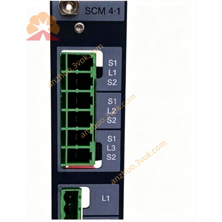
5.2 Terminal Wiring (Simplified)
| Terminal Group | Description | Wire Gauge |
|---|---|---|
| Auxiliary Power | ||
| 1–2 | 24 VDC (+/−) | 1.5 mm² |
| 3 | Chassis ground (PE) | 2.5 mm² |
| Delomatic‑3 Bus | ||
| 4–5 | Bus communication (A/B) | 1.0 mm² (twisted‑pair) |
| Digital Outputs (CH1–CH8) | ||
| 6–7 | CH1: NO/COM | 2.5 mm² |
| 8–9 | CH2: NO/COM | 2.5 mm² |
| 10–11 | CH3: NO/COM | 2.5 mm² |
| 12–13 | CH4: NO/COM | 2.5 mm² |
| 14–15 | CH5: NO/COM | 2.5 mm² |
| 16–17 | CH6: NO/COM | 2.5 mm² |
| 18–19 | CH7: NO/COM | 2.5 mm² |
| 20–21 | CH8: NO/COM | 2.5 mm² |
Bus Cable: Use twisted‑pair shielded cable for Delomatic‑3 bus; ground shield at controller end only.
Output Wiring: Keep high‑power cables as short as possible; avoid parallel runs with sensitive signals.
Terminal Torque: Tighten terminals to 0.8–1.0 Nm to prevent loose connections.
Load Protection: Install external fuses (10 A max) for each output channel if switching inductive loads.
6. Front Panel & Operation
6.1 Front Panel Layout
LED Indicators (Left to Right)
POWER: On = 24 VDC supply OK.
BUS: Flashing = Bus communication active; Solid = Bus fault.
FAULT: On = Overload/short‑circuit on any channel.
CH1–CH8: On = Output energised (relay closed).
6.2 Startup & Configuration
Physical Installation: Mount OPM‑1 on DIN rail; connect 24 VDC, bus, and output wiring.
Bus Recognition: Power on Delomatic‑3 controller; OPM‑1 is auto‑detected (no manual addressing).
Output Mapping: Use Delomatic‑3 controller HMI or DEIF PICUS software to assign logical functions (e.g., “Gen Breaker Close”) to CH1–CH8.
Protection Settings: Configure overload/short‑circuit thresholds (default: 10 A / 500 ms) via PICUS.
Test Outputs: Manually activate each channel via controller HMI; verify CHx LED and relay operation.
6.3 Normal Operation
POWER: Continuously On.
BUS: Flashes every 1 second (normal communication).
CH1–CH8: On/Off per controller commands (e.g., breaker open/close).
FAULT: Off (no faults); On if any channel trips (overload/short‑circuit).
7. Safety Precautions
High Voltage Hazard: Only qualified electrical personnel may install/service. Disconnect all power sources (24 VDC + high‑power outputs) before wiring.
Relay Load Ratings: Do not exceed 250 VAC / 8 A per channel; inductive loads (e.g., contactors) require external surge suppression.
ESD Sensitivity: Static electricity can damage internal PCB. Use anti‑static wristband and grounded ESD mat.
No Unauthorised Modification: Do not open the enclosure or modify internal circuits. Tampering voids warranty and may cause unsafe operation.
Environmental Limits: Do not operate outside –20 °C to +70 °C (standard) or –40 °C to +70 °C (marine).
8. Maintenance & Storage
8.1 Regular Maintenance (Every 6 Months)
Visual Inspection: Check for loose terminals, damaged wiring, corrosion, or overheating signs (discolouration).
Cleaning: Wipe front panel with dry lint‑free cloth; no liquid cleaners (avoid water ingress).
LED Check: Verify POWER/BUS/FAULT/CH1–CH8 LEDs operate correctly.
Relay Test: Manually activate each output; listen for relay click and confirm load operation.
Terminal Tightness: Retorque all terminals to 0.8–1.0 Nm.
Bus Communication: Verify BUS LED flashing; check for communication errors via PICUS.
8.2 Storage Guidelines
Packaging: Store in original anti‑static packaging with desiccant.
Environment: 10–30 °C, 30–70% RH, dry, clean, and dust‑free.
Protection: Avoid direct sunlight, extreme temperatures, and mechanical shock/vibration.
Duration: Shelf life ≤2 years. Inspect for ESD damage and test basic functions before use if stored longer.
9. Troubleshooting
| Fault Phenomenon | Possible Cause | Solution |
|---|---|---|
| POWER LED Off | No 24 VDC / blown internal fuse | Check power wiring; replace 3 A fuse |
| BUS LED Solid (Fault) | Bus wiring fault / incorrect polarity / controller offline | Check A/B wiring; reverse polarity; restart controller |
| FAULT LED On | Overload/short‑circuit on CH1–CH8 | Disconnect loads; test each channel; replace external fuse |
| CHx LED On 但无输出 | Relay contact worn / loose output wiring | Replace OPM‑1; retorque terminals |
| No Output Mapping | OPM‑1 not detected by controller / incorrect PICUS config | Reconnect bus; rescan devices; reassign outputs |
| Random Output Trips | Inductive load surge / insufficient suppression | Install RC snubber or freewheeling diode |
10. Warranty & Disclaimer
Model: OPM‑1 Digital Output Module (Delomatic‑3).
Warranty Period: 24 months from delivery date (normal installation/use per manual).
Warranty Exclusions: Misuse, overvoltage, lightning, water ingress, unauthorised modification, improper maintenance, or inductive load damage.
Specifications Subject to Change: Manufacturer reserves the right to update specifications without prior notice.
Liability Limitation: Manufacturer is not liable for indirect or consequential damages (e.g., downtime, lost revenue, equipment damage).
Documentation Version: 1.0 (2026); latest manual and firmware available at www.deif.com.
Get a Quote