BM-1000-PM1K
Description
1. Product Overview
Model: BM‑1000‑PM1K (ProSoft Technology)
Function: DIN‑rail high‑performance programmable module
Multi‑protocol support: EtherNet/IP, Modbus RTU/TCP, ASCII, custom protocols
Purpose: Add flexible communication and I/O expansion to Allen‑Bradley or third‑party PLCs; ideal for custom protocol conversion and legacy device integration.

2. Key Features
Communication Interfaces
Ethernet: 10/100 Mbps (RJ45), EtherNet/IP adapter, Modbus TCP client/server
Serial: RS‑232/422/485 (terminal block), Modbus RTU, ASCII, DF1
USB: Micro‑USB (config, firmware update)
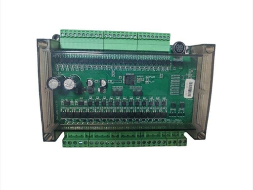
I/O Capacity
Digital I/O: 32 channels (configurable in/out)
Analog I/O: Optional (via expansion)
High‑speed: Pulse input/output, event capture
Programmability
Runtime: ProSoft “Programmable Application” (C‑like language)
Memory: 512 KB Flash, 128 KB RAM
Storage: MicroSD card (data logging, config backup)
General
Operating modes: Standalone, EtherNet/IP adapter, Modbus gateway
Industrial temp: ‑20°C to +60°C
Certifications: CE, UL, RoHS
3. Specifications
Power
18–30 VDC, 150 mA @ 24 VDC, ≤ 4 W
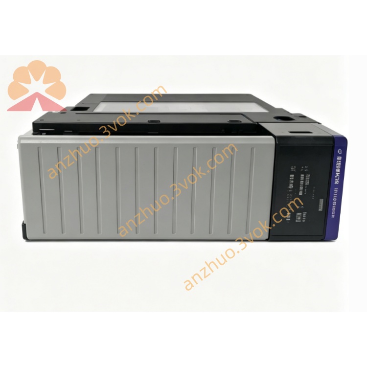
Physical
35 mm DIN rail, approx. 110 × 75 × 40 mm, IP30
Interfaces
Ethernet: RJ45, 10/100 Mbps
Serial: Terminal block (RS‑232/422/485)
USB: Micro‑USB (device)
I/O: 32‑pin terminal block (digital)
4. LED Indicators
PWR: solid = power OK
NET: flashing = Ethernet active
COM: flashing = serial communication active
STS: system status (heartbeat)
ERR: on = fault (comm/config/program)
5. Installation & Wiring
Mount on DIN rail in cabinet (vertical orientation).
Connect 18–30 VDC (observe polarity; use 24 VDC recommended).
Connect Ethernet to control network (EtherNet/IP or Modbus TCP).
Wire serial port to legacy devices (RS‑232/422/485; shielded cable recommended).
Connect digital I/O to field sensors/actuators (24 VDC logic).
Configure via web server (default IP: 192.168.1.100) or ProSoft Configuration Builder.
Load custom program (if used), save config, reboot.
6. Operating Modes
EtherNet/IP Adapter: Connects to ControlLogix/CompactLogix; data mapped to tags
Modbus Gateway: RTU ↔ TCP, master/slave
Programmable Standalone: Runs custom C code for protocol conversion, data logging, or control
7. Application
Protocol conversion: Legacy serial (ASCII, DF1) ↔ EtherNet/IP/Modbus
Data logging: Industrial data to SD card or cloud
Remote monitoring: Field devices to SCADA/HMI
OEM integration: Custom communication for machinery
8. Safety Notes
Wiring only when powered off; isolate power before installation.
Use shielded cable for serial/Ethernet; proper grounding to avoid EMI.
Do not exceed 30 VDC on power terminals.
Install in clean, dry area; avoid high humidity, dust, and direct sunlight.
Configuration/programming by qualified personnel.
Get a Quote