5201-DFNT-ASCII
Description
1. Product Overview
Part Number: 5201‑DFNT‑ASCII
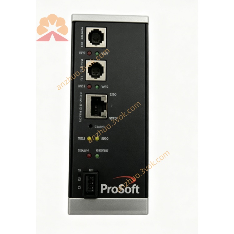
Manufacturer: ProSoft Technology (ProLinx 5000 Series)
Product Type: DIN‑rail mounted standalone protocol gateway
Function: Bidirectional data bridge between EtherNet/IP (Explicit Messaging) and generic ASCII serial devices (RS‑232/422/485). Enables Rockwell PLCs / EtherNet/IP systems to exchange ASCII strings with serial printers, displays, scales, scanners, meters, and custom ASCII devices.
Ports: 1 × 10/100 Ethernet (EtherNet/IP); 1 × configurable ASCII serial port (DB‑9)
2. Key Features
EtherNet/IP Client/Server (Explicit Messaging) – connects to Rockwell PLCs & EtherNet/IP hosts
Generic ASCII Serial (RS‑232/422/485 software selectable)
Serial baud: 1200–115.2 kbps; 8N1/8E1/8O1 configurable
ASCII framing control: user‑defined start/end characters, fixed length, timeout termination
Modes: Receive‑Only, Transmit‑Only, Transmit‑Receive
EtherNet/IP data mapping: ASCII strings ↔ EtherNet/IP tags (strings, bytes, words)
Support for RTS/CTS handshaking and RTS on/off timing
Swap byte order for endianness compatibility
Industrial isolation, surge protection, and EMC compliance
Wide temperature: −20 °C to +60 °C; DIN‑rail mount
LED status indicators for power, run, Ethernet, serial, fault
Configuration via ProSoft Configuration Builder (PCB) softwareProSoft Technology Inc
3. Technical Specifications
3.1 Power
Voltage: 18–32 VDC (24 VDC nominal)
Current: ≤500 mA @ 24 VDC
Power consumption: ≤12 W
3.2 EtherNet/IP (DFNT) Interface
Interface: 10/100Base‑T (RJ45), auto‑MDI‑X
Protocol: EtherNet/IP Explicit Messaging (Client/Server)
Connections: up to 32 concurrent EtherNet/IP connectionsProSoft Technology Inc
Data types: string, byte, word, dword, float
Function: read/write tags, unsolicited data, message routing
3.3 ASCII Serial Interface (Port 0)
Interface: RS‑232 / RS‑422 / RS‑485 (software selectable)
Connector: DB‑9 male
Baud rate: 1200, 2400, 4800, 9600, 19.2k, 38.4k, 57.6k, 115.2k
Data/Stop/Parity: 8N1, 8E1, 8O1; 7N2 optional
Handshaking: RTS/CTS, XON/XOFF, or none
Rx termination: fixed length, timeout, or user‑defined chars (e.g., CR/LF, ETX)
Tx: immediate or scheduled; minimum delay between transmits
3.4 Environmental
Operating temp: −20 °C to +60 °C
Storage temp: −40 °C to +85 °C
Humidity: 5–95% RH, non‑condensing
Vibration: 5 g, 10–150 Hz
Shock: 30 g (operational)
3.5 Physical
Mounting: standard 35 mm DIN rail
Dimensions: approx 125 × 80 × 30 mm
Weight: approx 0.45 kg
Certifications: CE, UL/cUL, Class 1 Div 2 (optional)
4. LED Indicators
PWR: Power – steady = OK
RUN: Module – flashing = running normally
ETH: EtherNet/IP – flashing = link/activity
SER: ASCII serial – flashing = data Tx/Rx
ERR: Fault – ON = config/comm error
5. Installation & Wiring
Mount gateway on DIN rail in cabinet.
Connect 24 VDC power (observe polarity).
Connect Ethernet cable to RJ45 for EtherNet/IP network.
Wire DB‑9 serial port to ASCII device (RS‑485 recommended for multi‑drop).
Set serial parameters (baud, parity, handshaking) via PCB.
Configure EtherNet/IP IP, subnet, and tag mappings.
Define ASCII framing (start/end chars, length, timeout).
Download configuration; verify LED status and data exchange.
6. Data Mapping & Operation
EtherNet/IP → ASCII: PLC writes string/bytes to gateway; gateway transmits over serial with defined framing.
ASCII → EtherNet/IP: Serial data received, stripped of framing, sent to PLC as string/bytes.
Termination examples: CR (0x0D), LF (0x0A), ETX (0x03), or 100 ms timeout.
Handshaking: RTS/CTS for flow control; RTS on/off delays configurable.
7. Typical Applications
Factory automation: Connect PLCs to ASCII printers, displays, and scanners
Logistics: Integrate serial scales, barcode readers into EtherNet/IP systems
Building automation: Bridge HVAC ASCII controllers to EtherNet/IP PLCs
Energy: Connect serial meters, analyzers to Rockwell control systems
Food & beverage: Serial recipe terminals and label printers on EtherNet/IP
8. Safety Notes
Disconnect power before installation/wiring.
Use shielded cables for Ethernet and serial ports.
Do not exceed voltage and temperature ratings.
Terminate RS‑485 bus at both ends.
Configuration must be performed by qualified personnel.
Get a Quote