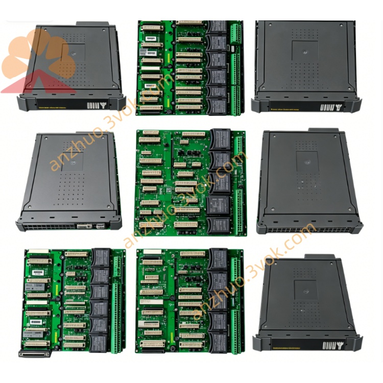
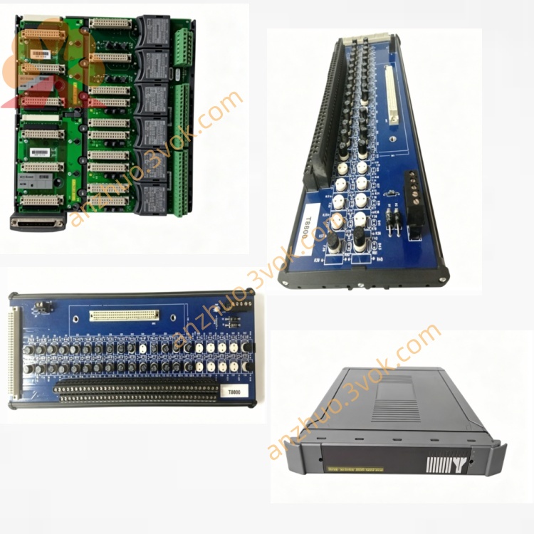
T8403
Description
1. Introduction
Purpose: Monitor discrete 24 VDC field devices (switches, proximity sensors, relay contacts)
Architecture: TMR (3‑2‑0) + 1oo2D voting per channel
Safety: IEC 61508 SIL 3 / SIL 4 certified
Channels: 40 × 24 VDC digital inputs
Isolation: 2500 V DC channel‑to‑channel & channel‑to‑system
Diagnostics: Per‑channel line monitoring (open/short circuit)
SOE: 1 ms resolution sequence‑of‑events logging
Hot‑Swap: Yes (online replacement)
2. Product Overview
40 × 24 VDC digital input channels (sink/source configurable)
Fully triplicated (TMR) input processing (three independent measurement lanes)
Sigma‑delta ADCs for high‑precision voltage sampling
Per‑channel 1oo2D voting for fault detection
Optical isolation (2500 V DC) between field and backplane
Onboard SOE (1 ms) for event time‑stamping
Independent line monitoring (open/short circuit) per channel
Conformal coated variant (T8403C) available for harsh environments
3. Specifications
3.1 Mechanical
Form Factor: T8000 chassis module (56 mm wide, 6U)
Dimensions (H×W×D): 255 mm × 56 mm × 210 mm
Weight: 1.2 kg (2.65 lbs)
Mounting: T8100 / T8400 chassis slots (1–16)
Connectors: Front‑panel terminal blocks (field inputs)
PCB Protection: T8403 = standard; T8403C = conformal coated (acrylic)
3.2 Electrical
System Supply: 20–32 V DC (nominal 24 V DC)
Power Consumption: ≤ 4 W
Input Channels: 40 × 24 VDC digital inputs
Input Voltage Thresholds:
Logic 1: 18–60 V DC
Logic 0: <5 V DC
Input Current: ~5 mA per channel (at 24 V DC)
Input Type: Sink (NPN) / Source (PNP) configurable
Isolation: 2500 V DC optical barrier (channel–channel, channel–system)
Backplane Interface: Trusted Backplane Bus (TBB), TMR
3.3 Functional
Voting: 1oo2D per channel (triple measurement + comparison)
SOE Resolution: 1 ms (per channel state change)
Diagnostics:
Open‑circuit detection (per channel, with line resistor)
Short‑circuit detection (per channel)
Onboard BIST (Built‑In Self‑Test)
Fault logging to system HMI
Response Time: ≤ 1.5 ms (channel to backplane)
Data Integrity: BER < 10⁻¹²
3.4 Environmental
Operating Temp:
T8403: 0 °C to +60 °C
T8403C: –40 °C to +70 °C
Storage Temp: –40 °C to +85 °C
Humidity: 5–95 % RH, non‑condensing
Altitude: ≤ 2000 m
Vibration: IEC 60068‑2‑6 (1 g, 10–150 Hz)
Shock: IEC 60068‑2‑27 (15 g, 11 ms)
3.5 Safety & Certification
Safety Standard: IEC 61508 SIL 3 / SIL 4
Certifications: CE, UL, CSA, ATEX II 3G Ex ec IIC T4 Gc, IECEx
Fault Tolerance: TMR (3‑2‑0), 1oo2D per channel
PFHd: < 5.0 × 10⁻¹⁰ / h (SIL 4)
4. Front Panel & Indicators
4.1 Front Panel LEDs
PWR (Green): On = Module power OK; Off = No power
RUN (Green): On = Module active; Flashing = Initialization
FAULT (Red): On = Module/channel fault; Flashing = Minor fault
COM (Green): Flashing = Backplane communication active
4.2 Front Panel Connectors
TB1–TB5: 5 × terminal blocks (8 channels each, 24 VDC inputs)
FG: Functional Ground (chassis earth)
5. Compatibility & System Architecture
5.1 Compatible Chassis
T8100: Trusted Processor Chassis
T8400: Trusted Controller Chassis
5.2 Compatible Controllers
T8111C: Trusted Processor Module
T8151C: Trusted Safety Processor Module
5.3 System Topology (TMR)
Field Devices → T8403 (40 DI) → Trusted Backplane (TBB) → T8111C/T8151C
Redundancy: 3 × T8403 modules (one per TMR lane) in SIL 4 systems
6. Installation
6.1 Chassis Mounting
Align T8403 with empty slot in T8100/T8400 chassis.
Insert module firmly until backplane connector seats.
Tighten front‑panel screws (torque 0.8–1.0 Nm).
Verify PWR + RUN LEDs ON after power‑up.
6.2 Field Wiring (24 VDC Inputs)
For each terminal block (TB1–TB5):
Connect 24 VDC + to group common terminal.
Connect field device output to channel input terminal.
Connect device common to 0 VDC / GND.
Use 16–22 AWG stranded wire; torque terminals to 0.5–0.6 Nm.
For open‑circuit detection: Install 10 kΩ line‑monitoring resistors (per channel).
Verify input status via system HMI after wiring.
6.3 Hot‑Swap Procedure
Identify faulty T8403 via FAULT LED or HMI alarm.
Loosen front‑panel screws; pull module out slowly.
Insert new T8403; tighten screws.
System auto‑detects new module; no shutdown required.
7. Operation & Diagnostics
Power‑up: PWR ON; RUN flashes during self‑test (5–10 s).
Normal Operation: PWR + RUN steady GREEN; FAULT OFF; COM flashing.
Fault Conditions:
FAULT ON: Channel short/open, TMR mismatch, or module failure.
FAULT Flashing: Minor fault (e.g., single‑lane mismatch).
SOE Logging: All state changes time‑stamped (1 ms) and stored in system memory.
8. Maintenance & Troubleshooting
8.1 Routine Maintenance
Quarterly: Check LED status; verify wiring tightness.
Annually: Inspect terminal blocks for corrosion; clean front panel.
8.2 Common Issues
PWR LED Off: Check chassis 24 VDC supply; verify module seating.
RUN LED Flashing: Module self‑test failed; re‑seat or replace.
FAULT LED On:
Channel open: Check field wiring/device; verify line resistor.
Channel short: Inspect wiring for shorts; replace device.
TMR mismatch: Replace faulty module.
No Input Response: Check group 24 VDC supply; verify wiring polarity.
9. Safety & Compliance
Install only in Trusted T8000 SIS environments.
Comply with IEC 61508 SIL 3 / SIL 4 system requirements.
Use isolated power supplies for field 24 VDC inputs.
Conformal coated (T8403C) for harsh environments (condensation, dust, chemicals).
10. Ordering Information
T8403: Trusted TMR 24 VDC DI Module (40‑Ch, standard)
T8403C: Trusted TMR 24 VDC DI Module (40‑Ch, conformal coated)
TC‑8403: Terminal Block Cable Kit (field wiring)
T8100: Trusted Processor Chassis
T8400: Trusted Controller Chassis
Get a Quote