T8312-4
Description
1. Introduction
Purpose: Physical IMB (Inter‑Module Bus) interface between controller and expander chassis
Architecture: Passive shielded adapter (TMR system extension)
Safety: Designed for IEC 61508 SIL 3 / SIL 4 TMR systems
Variant: T8312‑4 = up to 4 × T8300 (T8312‑7 supports up to 7)
Mounting: Rear of T8100/T8400 controller chassis
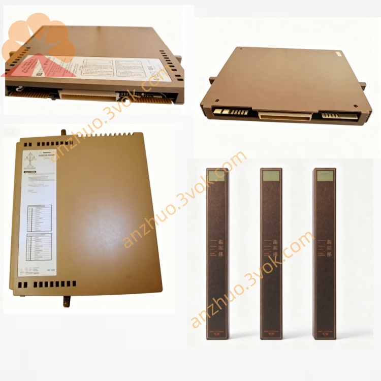
2. Product Overview
One 96‑way C‑type connector (SK1) to the controller chassis rear I/O
Four 12‑pin ODU circular connectors (numbered 1–4) for T8300 expander chassis
Integrated EMC shielding (conductive metal housing)
Spring clip mounting with release button (tool‑less installation)
Locking ODU connectors for vibration resistance
3. Specifications
3.1 Mechanical
Dimensions (H×W×D): 245 mm × 120 mm × 55 mm (approx.)
Weight: 2.0 kg (4.4 lbs)
Enclosure: EMC‑shielded steel, conductive gaskets
Mounting: Clips to rear of T8100/T8400 chassis (release button for removal)
Connector (Controller Side): 96‑way C‑type (SK1)
Connectors (Expander Side): 4 × 12‑pin ODU (labeled 1,2,3,4)
3.2 Electrical
Signal Interface: IMB (Inter‑Module Bus), 250 Mbps
Cable Type: TC‑301 shielded twisted pair
Isolation: 2500 V DC (system ↔ field)
Termination: Passive, impedance‑matched
Power: No internal power (passive device)
3.3 Environmental
Operating Temp: 0 °C to +60 °C (32 °F to 140 °F)
Storage Temp: –25 °C to +70 °C (–13 °F to 158 °F)
Humidity: 5–95 % RH, non‑condensing
Altitude: ≤ 2000 m
Vibration: IEC 60068‑2‑6 (1 g, 10–150 Hz)
Shock: IEC 60068‑2‑27 (15 g, 11 ms)
EMC Compliance: IEC 61000‑6‑2, IEC 61000‑6‑4 (fully shielded)
3.4 Performance
Max Expander Chassis: 4 × T8300
Max Cable Length: 30 m (TC‑301 copper)
IMB Data Rate: 250 Mbps (full‑duplex)
Connector Locking: ODU connectors with screw lock (vibration proof)
4. Front / Rear Panel & Connectors
4.1 Controller Side (Rear)
SK1: 96‑way C‑type connector → plugs into T8100/T8400 rear IMB port
4.2 Expander Side (Front)
Connector 1: ODU 12‑pin → T8300 #1
Connector 2: ODU 12‑pin → T8300 #2
Connector 3: ODU 12‑pin → T8300 #3
Connector 4: ODU 12‑pin → T8300 #4
4.3 Mounting Features
Spring clips: Secure to chassis rear
Release button: Press to remove unit (no tools)
5. Compatibility & Accessories
5.1 Compatible Controllers
T8100: Trusted Processor Chassis
T8400: Trusted Controller Chassis
5.2 Compatible Expander Modules
T8310: Expander Processor
T8311C: Expander Interface Module
5.3 Compatible Expander Chassis
T8300: 6U Expander Chassis (14 I/O slots)
5.4 Required Cables
TC‑301: 30 m IMB copper cable (T8312‑4 ↔ T8300)
6. Installation
6.1 Mounting to Controller Chassis
Locate the IMB expander port on the rear of T8100/T8400.
Align T8312‑4’s 96‑way SK1 connector with the chassis port.
Push firmly until spring clips engage (click sound).
Verify unit is securely clipped to chassis rear.
6.2 Connecting T8300 Expanders
Connect one end of TC‑301 to ODU connector 1 on T8312‑4.
Connect the other end to the IMB port on T8300 #1 rear panel.
Tighten ODU screw lock (hand‑tight only).
Repeat for connectors 2–4 (T8300 #2–#4).
Set each T8300 backplane DIP switch to unique ID (2–5).
6.3 Removal
Press the release button on T8312‑4 side.
Pull unit straight back (disconnects from chassis).
Unplug TC‑301 cables.
7. Operation & Diagnostics
Passive Routing: T8312‑4 does not process data; it routes IMB signals between T8310/T8311C and T8300.
Fault Indication: All IMB link faults are reported via T8310/T8311C front‑panel LEDs (OK/FAULT).
No Configuration: T8312‑4 requires no software setup; it is plug‑and‑play.
8. Maintenance & Troubleshooting
8.1 Routine Maintenance
Quarterly: Check ODU connector tightness and chassis clip security.
Annually: Inspect shielding gaskets for wear; clean with dry lint‑free cloth.
8.2 Common Issues
IMB Link Fault (T8310/T8311C FAULT LED On):
→ Check TC‑301 cable connections; verify ODU locks are tight; reseat T8312‑4.
No Expander Communication:
→ Ensure T8300 is powered; check DIP switch IDs; replace TC‑301 cable.
Vibration‑Related Errors:
→ Tighten ODU screw locks; confirm T8312‑4 is fully clipped to chassis.
9. Safety & Compliance
Install only in Trusted T8000 SIS environments.
Comply with IEC 61508 SIL 3 / SIL 4 system requirements.
Use only TC‑301 shielded cables; avoid unapproved cables.
Certifications: CE, UL, CSA, ATEX II 3G Ex ec IIC T4 Gc, IECEx.
Get a Quote