T8311C
Description
Purpose: High‑speed communication & control for T8300 expander chassis
Architecture: TMR (3‑2‑0 fault tolerant), HIFT (Hardware Implemented Fault Tolerant)
Safety Certification: IEC 61508 SIL 3, TÜV Rheinland certified
Compatibility: T8100/T8400 main chassis, T8300 expander chassis, TC‑301 copper cable, T8240 power shelf
Max Expanders: 8 × T8300 per T8311C
2. Product Overview
TMR triple‑core processing for expander I/O data and diagnostics
250 Mbps high‑speed IMB master communication to T8300 chassis
Redundant 24 V DC power from main chassis backplane
Comprehensive fault diagnostics & real‑time status reporting
Hot‑swap support (online replacement without system shutdown)
3. Specifications
3.1 Mechanical
Form Factor: Single‑width T8000 module
Dimensions (H×W×D): 241 mm × 30 mm × 300 mm (9.5” × 1.2” × 11.8”)
Weight: 1.14 kg (2.51 lbs)
Mounting: Horizontal slot in T8100/T8400 main chassis (processor slot)
Construction: EMC‑shielded steel, hot‑swap latch
Coating: Conformal coated (MIL‑I‑46058C, IPC‑CC‑830)
3.2 Electrical
Supply Voltage: 20–32 V DC (nominal 24 V DC)
Power Consumption: 40 W typical, 54 W max
Backplane Current: 1.7 A @ 24 V DC
Communication Port: IMB (Expander), 250 Mbps
Cable: TC‑301 shielded twisted pair
Isolation: 2500 V DC (field ↔ system)
Clock Frequency: 50 MHz
3.3 Environmental
Operating Temperature: –5 °C to +60 °C (23 °F to 140 °F)
Storage Temperature: –25 °C to +70 °C (–13 °F to 158 °F)
Humidity: 5–95 % RH, non‑condensing
Altitude: ≤ 2000 m
Vibration: IEC 60068‑2‑6 (1 g, 10–150 Hz)
Shock: IEC 60068‑2‑27 (15 g, 11 ms)
Protection Rating: IP20 (board‑level), IP40 (cabinet‑mounted)
Hazardous Area: ATEX II 3G Ex ec IIC T4 Gc
3.4 Performance
Processor: 50 MHz TMR triple‑core CPU
Memory: 512 MB RAM, 16 GB SSD
Data Rate: 250 Mbps (IMB ↔ T8300)
Max Expander Chassis: 8
I/O Capacity: Up to 112 I/O modules (8 × 14 slots)
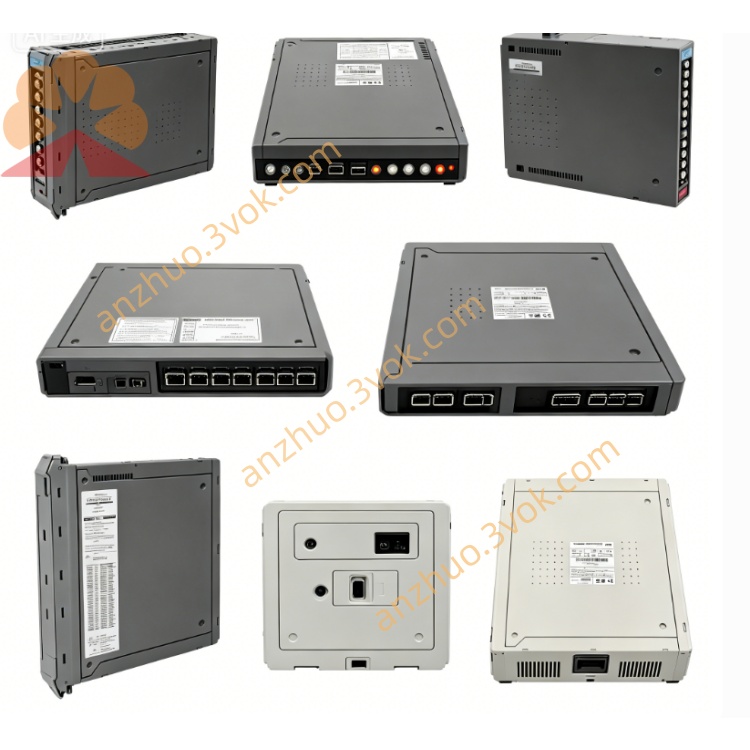
4. Front Panel & LED Indicators
LED Status (per slice: PWR, OK, FAULT)
PWR (Green): On = 24 V DC power OK; Off = No power
OK (Green): On = TMR health OK; Flashing = Minor fault (e.g., communication warning)
FAULT (Red): On = Critical fault (overvoltage, overtemperature, IMB loss, slice mismatch)
IMB (Expander) Port
Label: IMB (Expander)
Connector: RJ45‑style for TC‑301 cable
Status: Link/activity indicated by OK/FAULT LEDs
5. Compatibility & Accessories
5.1 Required Accessories
TC‑301: 30 m IMB copper cable (T8311C ↔ T8300)
T8300: 6U expander chassis (14 I/O slots)
T8240: 1U power shelf (24 V DC for T8300)
5.2 Compatible Main Chassis
T8100: Trusted Processor Chassis
T8400: Trusted Controller Chassis
5.3 Compatible I/O Modules (in T8300)
T8401: 16‑ch 24 V DC Digital Input
T8402: 16‑ch Digital Output (24 V DC)
T8403: 8‑ch Analog Input (4–20 mA)
T8404: 8‑ch Analog Output (4–20 mA)
T8451: 8‑ch RTD Input
T8461: 8‑ch Thermocouple Input
6. Installation (Hot‑Swap Supported)
6.1 Module Insertion
Align T8311C with guides in main chassis processor slot.
Push firmly until fully seated (backplane connector engaged).
Close front latch to secure.
The module will power on and begin TMR synchronization within 60 seconds.
6.2 IMB Cable Connection (T8311C ↔ T8300)
Connect one end of TC‑301 to the IMB (Expander) port on T8311C front panel.
Connect the other end to the IMB port on the rear panel of the target T8300.
Tighten connector screws; avoid sharp bends (min. bend radius = 8× cable diameter).
Set T8300 backplane DIP switches to unique addresses (2–8).
6.3 Hot‑Swap Replacement
Open front latch of faulty T8311C.
Pull module straight out (no power shutdown required).
Insert new T8311C (same part number) and close latch.
System will auto‑synchronize within 2 minutes; no reconfiguration needed.
7. Operation & Diagnostics
TMR Synchronization: On power‑up, three internal slices sync within 60 seconds.
Fault Tolerance: Any single slice failure triggers automatic reconfiguration (3‑2‑0) with no downtime.
Diagnostics: All faults are logged to the main system HMI and local LEDs.
Expander Control: T8311C polls all T8300 I/O modules, processes data, and communicates with the main controller.
8. Maintenance & Troubleshooting
8.1 Routine Maintenance
Quarterly: Check LED status, cable tightness, and latch security.
Annually: Clean front panel with dry lint‑free cloth; inspect connectors for wear.
8.2 Common Issues
PWR LED Off: Check main chassis 24 V DC supply; reseat module.
OK LED Flashing: Verify TC‑301 cable; check T8300 DIP switch address.
FAULT LED On: Replace T8311C; check for overheating or IMB short circuit.
No Expander Communication: Ensure T8300 is powered; reseat TC‑301 connectors.
9. Safety & Compliance
Install only in Trusted T8000 SIS environments.
Disconnect AC power before wiring (except hot‑swap module replacement).
Use shielded cables; comply with IEC 61000‑6‑2 / 6‑4.
Get a Quote