T8231
Description
Architecture: Full TMR (3‑channel per output, 2‑out‑of‑3 voting)
Safety: IEC 61508 SIL 3, TÜV certified; single‑point failure immune
Channels: 32 isolated digital outputs (sink, 24 V DC)
Hot‑Swap: Online replacement without shutdown
Diagnostics: Per‑channel short‑circuit/overload detection, line monitoring
Backplane: Trusted T8100/T8300 compatible
2. Specifications
2.1 Electrical
Output Voltage: 24 V DC nominal (backplane‑powered, 20–32 V DC)
Output Type: Sink (current flows into module; load between +24 V and output)
Channel Isolation: 2500 V DC (field ↔ system; channel‑to‑channel)
Output Current:
Per Channel: 0.5 A max (continuous)
Total Module: 10 A max
On‑State Resistance: <0.5 Ω
Leakage Current: <100 µA (off state)
Response Time: ≤4 ms (per channel)
Protection: Per‑channel electronic overcurrent, short‑circuit, overtemperature (auto‑reset)
Backplane Voltage: 20–32 V DC
2.2 Environmental
Operating Temp: –20 °C to +60 °C
Storage Temp: –40 °C to +85 °C
Humidity: 5–95 % RH (non‑condensing)
Altitude: Up to 2000 m
Vibration/Shock: IEC 60068‑2‑6/27 (industrial)
Protection: IP40 (chassis mounted)
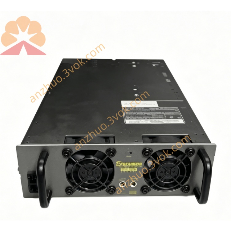
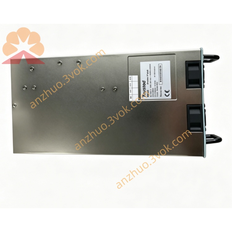
2.3 Mechanical
Form Factor: Single‑width module
Dimensions (H×W×D): 266 mm × 61 mm × 318 mm
Weight: ~1.8 kg
Mounting: Slides into chassis guides; front latch secured
Field Connector: Rear DIN41612 (32‑pin; 2×16 channels)
Backplane Connector: Trusted TMR backplane
3. Installation
3.1 Module Insertion (Hot‑Swap Enabled)
Select empty single‑width slot in T8100/T8300; remove blank panel.
Align T8231 with chassis guides; push firmly until seated.
Secure front latch.
Confirm PWR and OK LEDs (steady green = healthy).
3.2 Field Wiring (32 Sink Outputs)
Connector: Rear DIN41612 (pins 1–32; CH01–CH32)
Wiring Scheme (Sink):
+24 V: External positive to load (solenoid/relay coil)
CHxx: Load negative → module output (sink)
GND: Field/common ground
Cable: 18–22 AWG stranded, shielded (Belden 8760 or equivalent)
Shielding: Connect field shield to system earth at one point only (chassis PE)
Fusing: External 0.5–1 A fuse per channel recommended (field side)
3.3 Backplane & Grounding
Backplane: Redundant 24 V DC power + TMR communication
Grounding: Chassis PE to system earth; field GND isolated from chassis GND
4. Configuration (Trusted Workbench)
Connect PC with Trusted Workbench.
Select T8231 in hardware tree.
Set global parameters:
Output Mode: Sink (fixed for T8231)
Fault Response: Latch / Auto‑reset
Diagnostics: Enable short‑circuit/overload detection
Download configuration to module.
5. Front Panel Indicators
PWR (Green): Steady = Normal; Flashing = Backplane power fault
OK (Green): Steady = TMR vote healthy; Flashing = Single‑channel fault
FAULT (Red): On = Overcurrent/short circuit; Flashing = Isolation fault
CH01–CH32 (Yellow): On = Output active (ON); Off = Output inactive (OFF)
6. Operation
6.1 Normal Operation
T8231 uses TMR 2‑out‑of‑3 voting: each output command executed by three independent circuits; voted result drives field device.
Diagnostics monitor all channels; faults logged to system alarm list.
6.2 Fault Tolerance & Hot‑Swap
Single‑Channel Fault: System runs on two healthy circuits; OK LED flashes.
Module Failure: Hot‑swap replacement allowed; system online during swap.
Field Fault: Short/overload triggers FAULT LED; channel disabled (configurable).
7. Maintenance & Troubleshooting
7.1 Routine Maintenance
Quarterly: Inspect seating, latch tightness, LED status.
Annually: Clean with dry, lint‑free cloth; check cable connections and torque.
Diagnostics: Use Trusted Workbench to review fault logs and channel status.
7.2 Common Faults
PWR LED Off: Check backplane voltage (20–32 V DC); reseat module.
FAULT LED On: Identify shorted/overloaded channel via diagnostics; disconnect load and test; check external fuses.
OK LED Flashing: Single TMR channel fault; replace module at next scheduled maintenance.
CH LED On but Load Inactive: Verify +24 V supply to load; check wiring and load integrity.
CH LED Always Off: Confirm output command from controller; check channel diagnostics.
8. Safety & Compliance
Install only in Trusted T8100/T8300 safety chassis.
Disconnect field power before wiring (except hot‑swap replacement).
Use shielded cables; comply with IEC 61000‑6‑2/4.
Compliant with: CE, UL, CSA, IEC 61508 (SIL 3), TÜV certified.
Get a Quote