T8230
Description
Architecture: Full TMR (triple‑circuit per channel, 2‑out‑of‑3 voting)
Safety: IEC 61508 SIL 3, TÜV certified; single‑point failure immune
Channels: 32 isolated digital inputs (24 V DC nominal)
Hot‑Swap: Online replacement without system shutdown
Diagnostics: Per‑channel open/short‑circuit detection, line fault monitoring
Backplane: Trusted T8100/T8300 chassis compatible
2. Specifications
2.1 Electrical
Input Voltage: 24 V DC nominal (18–32 V DC range)
Input Type: Sink/source selectable (wet/dry contact)
Channel Isolation: 2500 V DC (field ↔ system; channel‑to‑channel)
Input Current: ~10 mA per channel (24 V DC)
Logic Threshold:
ON: ≥18 V DC
OFF: ≤6 V DC
Response Time: ≤4 ms (per channel)
Filtering: Software‑selectable (0, 8, 16, 32, 64, 128, 256, 512, 1024 ms)
Protection: Overvoltage, reverse polarity, short‑circuit (electronic, auto‑reset)
Backplane Voltage: 20–32 V DC
2.2 Environmental
Operating Temp: –20 °C to +60 °C
Storage Temp: –40 °C to +85 °C
Humidity: 5–95 % RH (non‑condensing)
Altitude: Up to 2000 m
Vibration/Shock: IEC 60068‑2‑6 / IEC 60068‑2‑7 (industrial)
Protection: IP40 (chassis mounted)
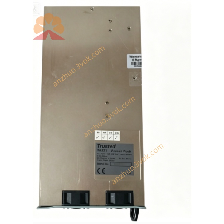
2.3 Mechanical
Form Factor: Single‑width module (Trusted standard)
Dimensions (H×W×D): 266 mm × 61 mm × 318 mm
Weight: ~1.8 kg
Mounting: Slides into T8100/T8300 chassis slot guides; front latch secured
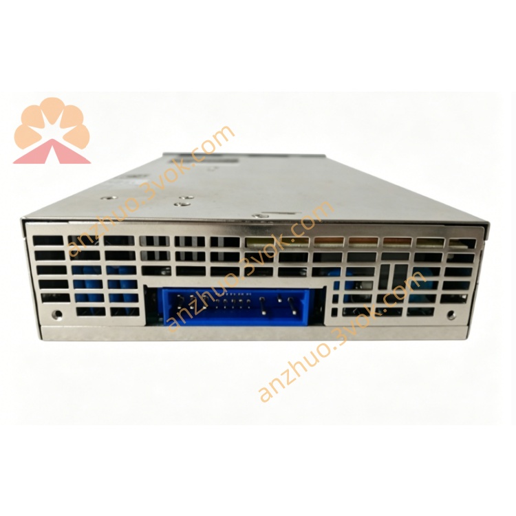
Field Connectors: Rear DIN41612 (32‑pin; 2×16 channels)
Backplane Connector: Trusted TMR backplane
3. Installation
3.1 Module Insertion (Hot‑Swap Enabled)
Select an empty single‑width slot in T8100/T8300 chassis; remove blank panel.
Align T8230 with chassis guides; push firmly until fully seated.
Secure front latch to lock module in place.
Confirm PWR and OK LEDs illuminate (steady green = healthy).
3.2 Field Wiring (32 Channels, 24 V DC)
Terminals: Rear DIN41612 (pins 1–32; 2 groups × 16 channels)
Wiring Scheme:
+24 V: Field positive (sink input)
GND: Field negative (common return)
CH01–CH32: Digital input signals
Cable: 18–22 AWG stranded, shielded (Belden 8760 or equivalent)
Shielding: Connect field shield to system earth at one point only (chassis PE)
Termination: No external fuses required (per‑channel electronic protection)
Wet vs. Dry:
Wet (24 V): Module provides +24 V to field switches (sink)
Dry (Contact): External 24 V source drives inputs (source)
3.3 Backplane & Grounding
Backplane: T8100/T8300 provides redundant 24 V DC power and TMR communication
Grounding: Chassis PE connected to system earth; field GND isolated from chassis GND
4. Configuration (via Trusted Workbench)
Connect PC with Trusted Workbench to the Trusted system.
Select T8230 in hardware tree.
Set global parameters:
Input Type: Sink (wet) / Source (dry)
Filter Time: 0–1024 ms (per channel or global)
Fault Response: Latch / Auto‑reset
Enable diagnostics:
Open‑circuit detection
Short‑circuit detection
Line voltage monitoring
Download configuration to module.
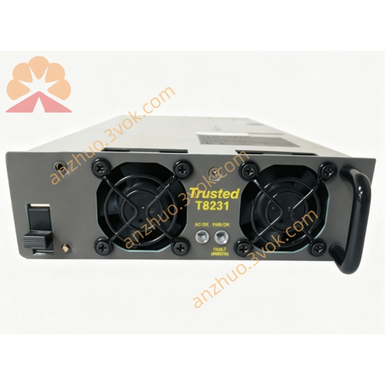
5. Front Panel Indicators
PWR (Green): Steady = Normal; Flashing = Backplane power fault
OK (Green): Steady = TMR vote healthy; Flashing = Single‑channel fault
FAULT (Red): On = Overcurrent/short circuit; Flashing = Isolation fault
CH01–CH32 (Yellow): On = Input active (ON); Off = Input inactive (OFF)
6. Operation
6.1 Normal Operation
T8230 operates in TMR 2‑out‑of‑3 voting mode; each input channel is read by three independent circuits.
Module outputs voted ON/OFF status to the Trusted controller.
Diagnostics continuously monitor all channels; faults logged to system alarm list.
6.2 Fault Tolerance & Hot‑Swap
Single‑Channel Fault: System continues operating with two healthy circuits; OK LED flashes.
Module Failure: Hot‑swap replacement allowed; system remains online during swap.
Field Fault: Open/short circuit triggers FAULT LED; channel disabled (configurable).
7. Maintenance & Troubleshooting
7.1 Routine Maintenance
Quarterly: Inspect seating, latch tightness, LED status.
Annually: Clean with dry, lint‑free cloth; check cable connections and torque.
Diagnostics: Use Trusted Workbench to review fault logs and channel status.
7.2 Common Faults
PWR LED Off: Check backplane voltage (20–32 V DC); reseat module.
FAULT LED On: Identify shorted/overloaded channel via diagnostics; disconnect field wiring and test.
OK LED Flashing: Single TMR channel fault; replace module at next scheduled maintenance.
CH LED Always Off: Verify field 24 V DC supply; check wiring and switch contacts.
CH LED Always On: Check for shorted field wiring or stuck switch.
8. Safety & Compliance
Install only in Trusted T8100/T8300 safety chassis.
Disconnect field power before wiring (except hot‑swap module replacement).
Use shielded cables for field wiring to reduce EMI; comply with IEC 61000‑6‑2/4.
Compliant with: CE, UL, CSA, IEC 61508 (SIL 3), TÜV certified.
Get a Quote