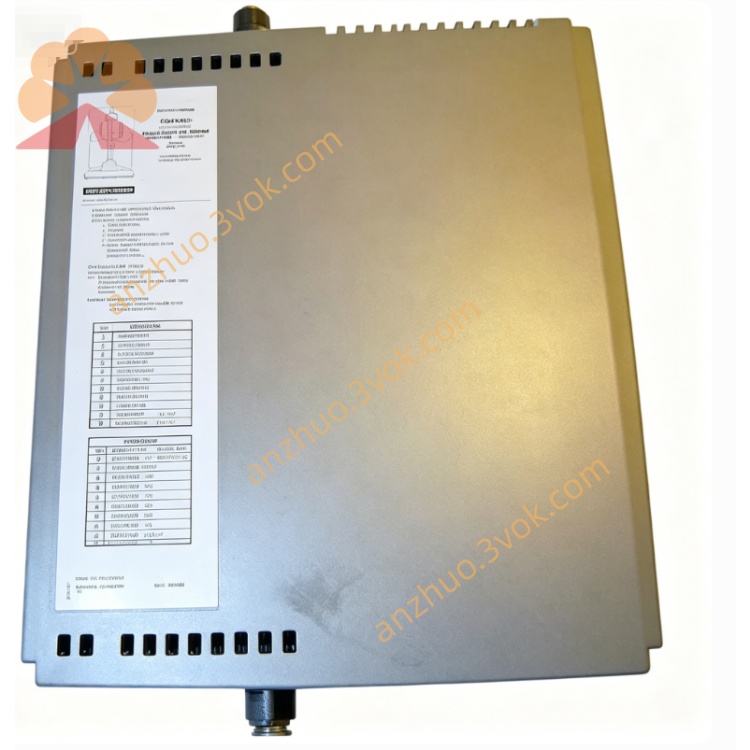
T3441A
Description
2. Key Features
16 isolated output channels, 24 VDC rated.
Hot‑swappable design for online replacement without system shutdown.
TMR (Triple Modular Redundancy) architecture, SIL 3 certified (IEC 61508).
Overload/short‑circuit protection per channel.
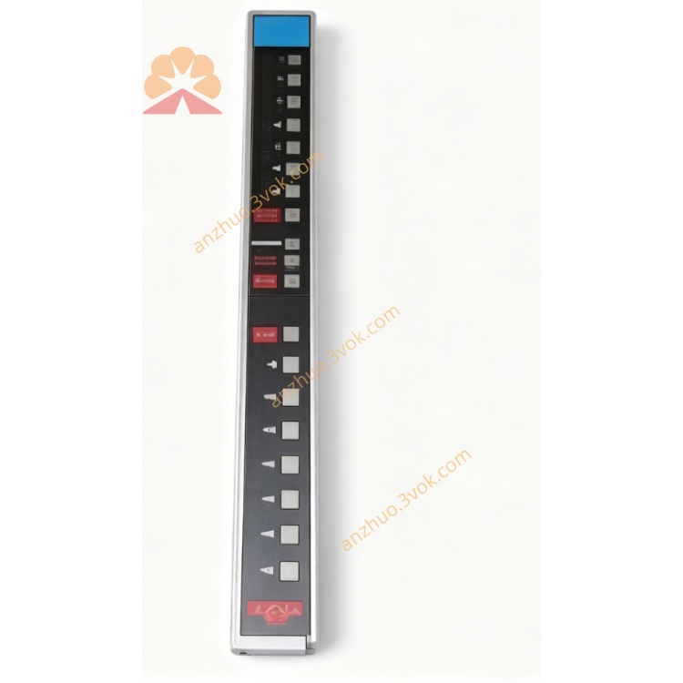
LED status indicators for power, fault, and individual channel state.
Wide operating temperature: −40°C to +70°C.
3. Technical Specifications
Model: T3441A
Manufacturer: Rockwell ICS Triplex
System Compatibility: Regent/Trusted T3 series control systems
Input Voltage: 24 VDC ±10%
Output Voltage: 24 VDC
Output Current: 2 A per channel; 32 A total
Isolation Voltage: 500 Vrms (channel‑to‑backplane)
Power Consumption: 2.5 W (max)
Operating Temperature: −40°C to +70°C
Storage Temperature: −40°C to +85°C
Humidity: 5%–95% non‑condensing
Shock: 30 g, 11 ms half‑sine
Vibration: 5 g, 10 Hz–500 Hz
Dimensions: 120 mm × 123 mm × 63 mm
Weight: 0.5 kg
Certifications: SIL 3 (IEC 61508), CE, UL
4. Installation & Wiring
4.1 Mechanical Installation
Mount the module in a standard ICS Triplex T3 series rack (slot 0–15).
Ensure proper grounding of the rack and module chassis.
Allow ≥25 mm clearance around the module for ventilation.
4.2 Wiring
Backplane Connector: Connect to the system backplane for power and communication.
Field Terminals:
Positive (+24 VDC) and negative (GND) power for field devices.
16 output channels (CH1–CH16) for device control.
Cable Requirements: Use 18–22 AWG stranded copper wire; torque terminals to 0.8–1.0 N·m.
Isolation: Separate field wiring from control wiring to avoid EMI.
5. Operation
5.1 Power‑Up
Apply 24 VDC power to the rack; the “PWR” LED lights green.
The module performs self‑diagnostics; the “FAULT” LED turns red if a fault is detected.
5.2 Normal Operation
Channel Control: Outputs are switched ON/OFF via the control system logic.
LED Indicators:
Green: Channel ON.
Off: Channel OFF.
Red: Channel fault (overload/short circuit).
5.3 Fault Handling
Channel Fault: The module disables the faulty channel; the “FAULT” LED lights red. Replace the field device or check wiring.
Module Fault: Communication failure or internal error. Check backplane connection or replace the module.
6. Maintenance
Regular Inspection: Check LED status, wiring tightness, and module temperature monthly.
Cleaning: Keep the module free of dust; use a dry cloth.
Calibration: No periodic calibration required.
Replacement: Use hot‑swap procedure: remove the faulty module, insert a new one, and verify operation.
7. Safety Precautions
ESD Protection: Wear a grounded wrist strap when handling the module.
Power Off Before Wiring: Disconnect power before connecting/disconnecting field wiring.
Load Ratings: Do not exceed 2 A per channel or 32 A total current.
Environmental Limits: Operate within −40°C to +70°C; avoid condensation.
Get a Quote