31C015-503-4-00
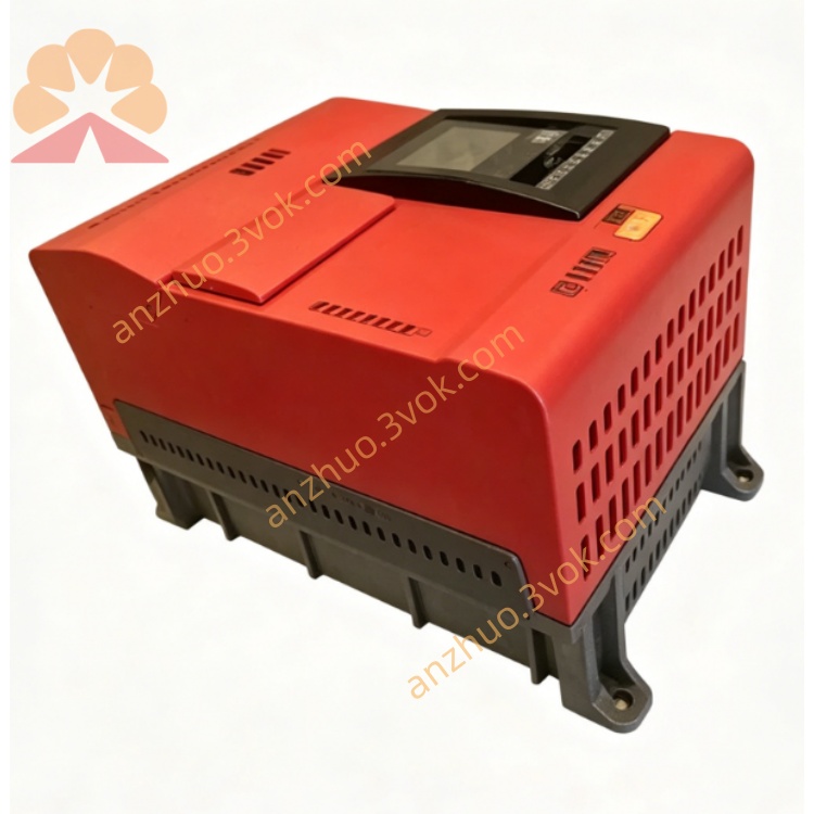
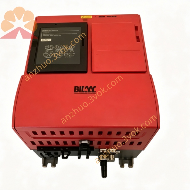
Description
1. Model Code Definition
2. Electrical Parameters
Rated Output Power: 1.5 kW
Input Voltage: 3-phase AC 380~500 V
Rated Frequency: 50 Hz / 60 Hz
Rated Continuous Output Current: 4.0 A
Output Voltage Range: 0~480 V three-phase AC
Output Frequency Range: 0~400 Hz
Control Mode: V/F open-loop control / Sensorless vector control
Overload Capacity: 150% rated current for 60 seconds
Switching Frequency: 4kHz, 8kHz, 12kHz, 16kHz optional
Standard equipped with STO Safe Torque Off function
3. Physical & Environmental Parameters
Protection Class: IP20
Cooling Method: Natural air cooling without fan
Operating Temperature: 0°C ~ +45°C for full load operation
Storage Temperature: -25°C ~ +70°C
Working Humidity: 5%~95%, non-condensing environment
Installation Method: Vertical wall mounting
Max Working Altitude: ≤1000 meters without power reduction
Weight: Approximately 2.5 kg
4. Standard Interfaces
Built-in RS485 interface, support Modbus RTU protocol
Analog speed signal: 0-10V DC / 0-20mA dual input
6 groups of programmable 24V DC digital input terminals
2 groups of programmable relay output terminals
PTC motor over-temperature protection input port
External brake resistor connection terminal
Multi-speed fixed frequency control terminals
Support external FBG31C operation panel for parameter setting
5. Main Functions
Adjustable acceleration and deceleration time: 0.1s ~ 600s
Integrated DC braking and dynamic braking for fast stop
Intelligent energy saving operating mode
Three control modes: local panel, external terminal, remote communication
Slip compensation to stabilize running speed under load
Soft start and soft stop to reduce starting current and mechanical impact
Built-in PID closed-loop control for constant speed and constant pressure
Support parameter saving, copying and one-click recovery
Stable high torque output at low speed
6. Complete Protection Functions
Instantaneous overcurrent and thermal overload protection
Over voltage and under voltage protection
Three-phase input phase loss detection protection
Inverter internal overheating protection
Electronic thermal motor overload protection
Output short circuit protection
Motor earth fault protection
Running anti-stall protection
ESD anti-static protection for control terminals
Hardware STO safety torque off protection
7. Installation & Wiring Rules
Cut off all power before wiring, debugging and maintenance
Separate power cables and control cables to avoid electromagnetic interference
Ensure reliable connection of PE grounding terminal
Reserve enough space around for heat dissipation
Do not install in dusty, humid, oily and corrosive places
Adopt shielded special motor cables for output connection
8. Commissioning Steps
Check all wiring to avoid wrong connection and short circuit risks
Confirm input power voltage matches inverter rated voltage
Set correct motor rated voltage, current, frequency and speed parameters
Select suitable control mode according to actual demands
Set reasonable acceleration/deceleration time and frequency limit
Conduct no-load test run and check motor running status
Put into formal load operation after stable operation
9. Daily Maintenance
Clean surface dust regularly every 3 to 6 months
Check tightness of all wiring terminals periodically
Observe real-time running current and temperature during operation
All inspection and maintenance shall be operated by qualified electricians
Get a Quote