31C011-503-4-20
Description
1. Model Code Definition
2. Electrical Parameters
Rated Output Power: 1.1 kW
Input Voltage: 3-phase AC 380~500 V
Rated Frequency: 50 Hz / 60 Hz
Rated Continuous Output Current: 3.2 A
Output Voltage Range: 0~480 V three-phase AC
Output Frequency Range: 0~400 Hz
Control Mode: V/F open-loop control / Sensorless vector control
Overload Capacity: 150% rated current for 60 seconds
Switching Frequency: 4kHz, 8kHz, 12kHz, 16kHz optional
Standard built-in STO Safe Torque Off function
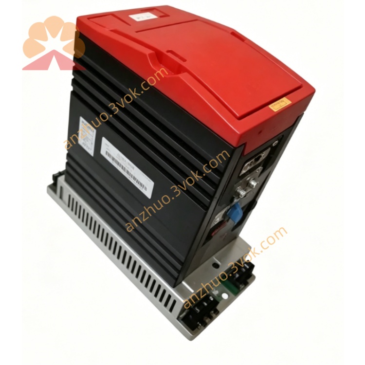
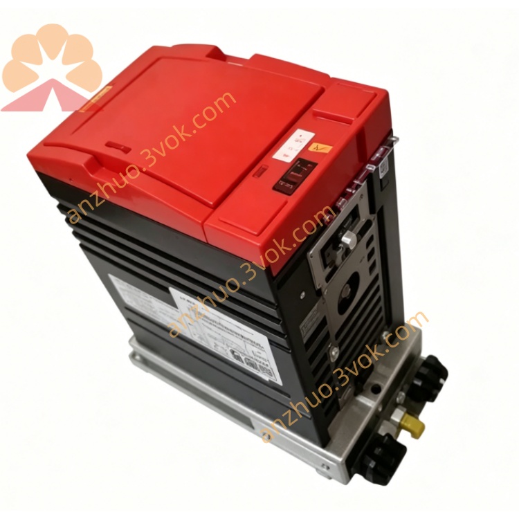
3. Physical & Environmental Parameters
Protection Class: IP20
Cooling Method: Natural air cooling without cooling fan
Operating Temperature: 0°C ~ +45°C under full load
Storage Temperature: -25°C ~ +70°C
Working Humidity: 5%~95%, non-condensing environment
Installation Type: Vertical wall mounting
Maximum Working Altitude: ≤1000 meters without power derating
Weight: Approximately 2.2 kg
4. Control Terminals & Communication Interfaces
Analog speed input: 0-10V DC / 0-20mA dual signal mode
6 sets of programmable 24V DC digital input terminals
2 sets of programmable relay signal output terminals
PTC motor over temperature protection input port
External brake resistor connection terminal
Multi-section fixed speed control terminals
Reserved RS485 Modbus RTU communication interface
Core configuration: Onboard integrated PROFIBUS-DP interface
PROFIBUS parameters: Adjustable station address, support standard GSD file, stable industrial bus transmission
No built-in operation panel, support external FBG31C keypad for parameter setting
5. Main Operating Functions
Adjustable acceleration and deceleration time range: 0.1 seconds to 600 seconds
Built-in DC braking and dynamic braking function for rapid stop
Intelligent energy-saving operation mode
Three control modes: external terminal control, fieldbus remote control, panel local control
Slip compensation function to ensure stable running speed under load
Soft start and soft stop design to reduce starting impact current and mechanical vibration
Integrated PID closed-loop control for constant speed and constant pressure application
Support parameter saving, copying and one-click restore functions
Excellent low-speed high-torque output performance
6. Complete Safety Protection System
Instantaneous overcurrent protection and thermal overload protection
Over voltage and under voltage fault protection
Three-phase input phase loss detection and protection
Inverter internal power module overheating protection
Electronic thermal type motor overload protection
Output loop short circuit fault protection
Motor side earth fault protection
Running anti-stall protection function
Static electricity protection for control terminals
Hardware-level STO safety torque off protection conforming to industrial safety standards
7. Installation & Wiring Requirements
Cut off all power supply before wiring, debugging and daily maintenance
Separate power main circuit cables and control signal cables to avoid electromagnetic interference
Ensure firm and reliable connection of PE grounding terminal
Reserve sufficient surrounding space for natural heat dissipation
Do not install in dusty, humid, oily mist and corrosive gas environment
It is recommended to use shielded special frequency conversion cables for motor output wiring
8. Standard Commissioning Steps
Check all wiring carefully to eliminate wrong connection and short circuit hidden dangers
Confirm that on-site input power voltage matches inverter rated voltage specification
Accurately set motor nameplate parameters including rated voltage, rated current, rated frequency and rated speed
Select PROFIBUS bus control or terminal control mode according to actual system requirements
Set reasonable acceleration/deceleration time and upper and lower limit frequency values
Perform no-load trial operation firstly to confirm motor running direction and operating sound
Gradually load operation and formally put into use after stable operation
9. Daily Maintenance Rules
Regularly clean surface dust every 3 to 6 months
Periodically check the fastening condition of all wiring terminals
Monitor real-time operating current and internal working temperature during operation
All equipment fault inspection and maintenance work must be operated by qualified professional electricians
Get a Quote