2658
Description
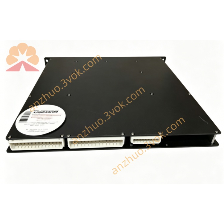
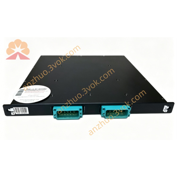
TRICONEX 2658
Tricon II Terminator Interface Module (TMR, SIL 3)
Official English Specification Manual (consistent format with 2651/2652)
1. General Description
2. Model Information
Model: 2658
Type: Terminator Interface Module (Tricon II)
System Series: Triconex Tricon / Trident
Safety Level: SIL 3 (IEC 61508)
Certification: TÜV, FM, CSA
Part Number: 7400096‑200
Status: Obsolete / Discontinued
3. Main Features
Tricon II System Termination Interface
Dedicated termination for Tricon II I/O and communication buses.
100 Ω RS‑485 Line Termination
Built‑in termination resistors to optimize signal integrity.
Triple Modular Redundancy (TMR) Compatible
Supports 2oo3 voting architecture for safety‑critical links.
24 VDC Powered Interface
Backplane or external 24 VDC supply.
High Noise Immunity
Reduces EMI/RFI interference on field communication lines.
N+1 Redundancy Support
Enhances system availability for continuous operation.
Hot‑Swappable
Online replacement without system shutdown.
4. Technical Parameters
4.1 Electrical
Supply Voltage: 24 VDC (nominal)
Input Current: 10 mA
Termination Resistance: 100 Ω (RS‑485)
Communication Standard: RS‑485 compatible
Isolation: Galvanic isolation between field and backplane
4.2 Redundancy & Safety
Architecture: TMR / N+1 redundancy
Safety Integrity Level: SIL 3
Fault Coverage: > 99% (diagnostics)
System Availability: 99.999%
4.3 Environmental
Operating Temperature: −40°C to +70°C
Storage Temperature: −40°C to +85°C
Relative Humidity: 5%–95% non‑condensing
Vibration: 5–200 Hz, 1 g
4.4 Physical
Dimensions: ~100 mm × 100 mm × 40 mm
Weight: ~0.5 kg
Mounting: Tricon / Trident baseplate, 19” rack
5. Function Overview
Signal Termination
Provides precise 100 Ω termination for RS‑485 communication lines, preventing signal reflection and noise.
TMR Interface Routing
Distributes and conditions signals between the three TMR channels.
Fault Detection & Reporting
Monitors line faults, open/short, and power supply anomalies; reports via TriStation.
SOE Timing
Supports time‑stamped event logging for communication and termination status changes.
6. LED Indicators
PWR (Green): 24 VDC power OK
RUN (Green): Module active, communicating
FAULT (Red): Termination/communication fault
TERM (Yellow): Termination active
7. Installation & Configuration
Insert 2658 into a Tricon II / Trident baseplate slot.
Connect RS‑485 field cables to the module’s termination ports.
Apply 24 VDC power (backplane or external).
Use TriStation 1131 to enable termination and set fault thresholds.
Verify: PWR + RUN green, no FAULT red.
8. Typical Applications
Tricon II SIS system communication bus termination
RS‑485 field network termination in SIL 3 loops
ESD/BMS system redundant communication links
Oil & gas, petrochemical, power plant safety I/O termination
Critical alarm and interlock signal conditioning
9. Maintenance
Hot‑swap faulty 2658 without system shutdown.
Inspect RS‑485 cables and termination connections.
Review fault logs and SOE records via TriStation.
Replacement: Contact Triconex for equivalent termination modules.
10. Compatibility & Ordering
Compatible Systems: Tricon II, Trident SIS
Configuration Software: TriStation 1131
Matching Terminal Base: Tricon II dedicated termination base
Model: 2658
Description: Tricon II Terminator Interface Module (100 Ω RS‑485, 24 VDC, SIL 3)
Get a Quote