2401
Description
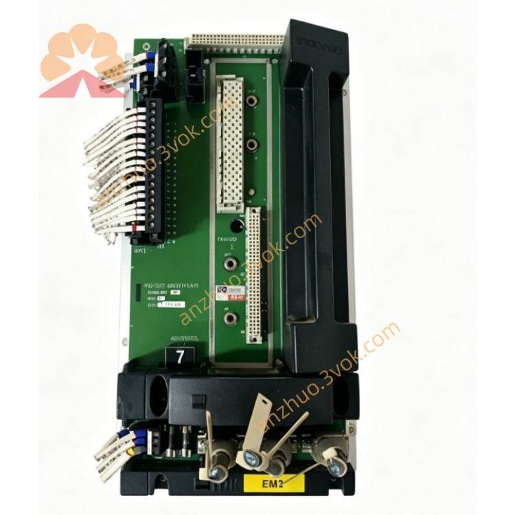
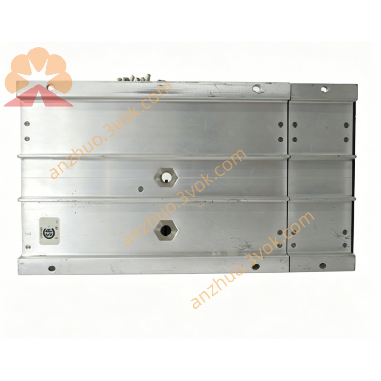
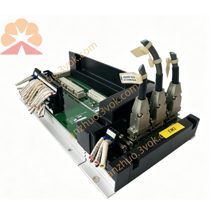
TRICONEX 2401
Digital Output Module (16‑Channel, TMR, 24VDC)
Official Specification & User Manual (English)
1. General Description
2. Part Number & Type
Model: 2401
Type: Digital Output Module (DO), TMR
Series: Trident (Triconex / Schneider Electric)
Safety Level: SIL 3 (IEC 61508)
Approvals: TÜV Rheinland, FM, CSA
3. Key Features
16 Isolated Digital Output Channels
Sinks/sources 24 VDC to field devices.
Triple Modular Redundancy (TMR)
Three independent output circuits per channel; 2oo3 voting ensures single‑point fault tolerance.
High Current Rating
Max 2 A per channel / 8 A per module (resistive load).
Short‑Circuit & Overload Protection
Electronic current limiting per channel; fault auto‑shutdown.
Hot‑Swappable
Replace module online without system shutdown.
Comprehensive Diagnostics
Open/load detection, short‑circuit alarm, and SOE time stamping (≤ 40 ms).
4. Technical Specifications
4.1 Output Channels
Number: 16 channels, isolated per channel
Signal Type: 24 VDC digital output (sink/source)
Voltage Range: 18–30 VDC (nominal 24 VDC)
Current: 2 A max per channel (resistive)
Response Time: ≤ 10 ms (on/off)
4.2 Safety & Redundancy
Architecture: Triple Modular Redundant (TMR), 2oo3 voting
Safety Integrity Level: SIL 3
Fault Coverage: > 99%
System Availability: 99.999%
4.3 Environmental
Operating Temperature: 0°C to +60°C
Storage Temperature: −40°C to +85°C
Humidity: 5%–95% non‑condensing
Vibration: 5–200 Hz, 1g
Protection Class: IP20 (module)
4.4 Power
Backplane Power: 5 VDC / 1.5 A (from Trident chassis)
Field Power: 24 VDC (user‑supplied, 18–30 VDC)
4.5 Physical
Dimensions: 133 mm × 114 mm × 32 mm (5.25” × 4.50” × 1.25”)
Weight: ~0.3 kg
Mounting: Trident baseplate, 19” rack compatible
5. Functional Overview
On/Off Control
Drives 24 VDC solenoids, emergency shutdown valves, relay coils, and motor contactors.
Triple Voting & Drive
Three independent output drivers per channel; majority‑voted command ensures correct state.
Diagnostics & Alarms
Detects open load, short circuit, overload; reports to TriStation with channel‑specific fault.
SOE Logging
Time‑stamps output state changes and faults for safety event analysis.
6. LED Indicators
PWR (Green): Module power OK
RUN (Green): Module active, communicating
FAULT (Red): Channel or module fault
CH 1–16 (Yellow): Channel ON state
7. Installation & Configuration
Insert 2401 into an empty Trident baseplate slot.
Connect field devices (solenoids, valves) to the 16‑channel terminal block.
Apply 24 VDC field power to the output loops.
Use TriStation 1131 to:
Enable/disable channels
Set fail‑safe state (ON/OFF on fault)
Configure fault thresholds (overload/short)
Verify LED status: PWR + RUN green, no FAULT red.
8. Typical Applications
Emergency Shutdown (ESD) valve control
Burner Management Systems (BMS) fuel valves
Safety interlock solenoids
Fire & gas suppression system triggers
HIPPS valve actuation
9. Maintenance
Hot‑swap faulty 2401 without shutdown.
Inspect wiring, terminals, and 24 VDC field power.
Review SOE and fault logs via TriStation.
Update firmware as needed.
10. Ordering Information
Model: 2401
Description: Triconex Trident 16‑Channel TMR Digital Output Module (24 VDC)
Compatible with: Trident Chassis, 2101/3700A MP Modules, TriStation 1131
Get a Quote