2058
Description
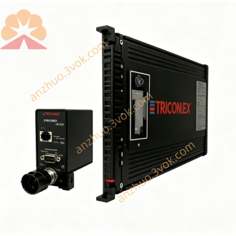
Model: TRICONEX 2058
Product Type: Communication Processor Module / TMR Industrial Control Module
1. Safety Instructions
This module belongs to safety‑critical TMR (Triple‑Modular Redundant) control equipment. Only qualified industrial automation engineers are allowed to install, wire, configure and maintain it.
Disconnect all power supplies (AC/DC) of the TRICON system chassis before module installation, removal or wiring.
Do not install or operate the module in environments with high temperature, high humidity, dust, corrosive gas, strong electromagnetic interference or vibration beyond rated limits.
Comply with IEC 61508, SIL3 safety standards and local electrical codes for hazardous area applications.
Avoid static electricity damage: wear anti‑static wristband when handling the module PCB.
2. Product Overview
Key Features
TMR redundant design, supports SIL3 safety integrity level certification
High‑speed industrial communication, compatible with Modbus, Ethernet, Profibus protocols
Front‑panel LED status indicators for real‑time fault diagnosis
Plug‑in design for TRICON standard chassis, easy hot‑swap maintenance
Industrial‑grade anti‑interference, suitable for oil & gas, chemical, power and petrochemical industries
3. Technical Specifications
Power Supply: 120/240 VAC or 125 VDC
Operating Temperature: 0℃ ~ +60℃; Storage Temperature: -40℃ ~ +85℃
Relative Humidity: 5%‑95%, non‑condensing
Communication Interface: TRICON internal backplane, external Ethernet/serial ports
Safety Certification: SIL3, IEC 61508, IEC 61511, UL, CSA, CE
Dimensions & Weight: Standard TRICON module size, approx. 2.5kg
4. Installation Guide
Power off the entire TRICON system chassis.
Insert TRICONEX 2058 module into the designated slot of the chassis, push firmly until locked.
Connect field wiring to terminal assemblies/termination panels strictly per system wiring diagram.
Check all wiring terminals for firm connection, no short‑circuit or open‑circuit risk.
Restore power supply after installation inspection, confirm module self‑test completes normally.
5. Operation & Configuration
After power‑on, observe front‑panel LEDs: green for normal operation, red for fault/alarm.
Configure communication parameters, control logic and diagnosis functions via TRICON system configuration software.
Real‑time monitor system running status; the module automatically conducts fault voting and redundancy switching when abnormal signals occur.
For safety interlock applications (ESD/BMS), strictly follow safety logic requirements for parameter setting.
6. Maintenance & Troubleshooting
Routine Maintenance
Keep module surface clean, dry and dust‑free.
Regularly check wiring terminals and backplane connectors for looseness or corrosion.
Conduct periodic self‑diagnosis testing via system software.
Common Faults & Solutions
Module power‑on self‑test failure: Check power supply voltage, backplane connection and anti‑static damage.
Communication interruption: Verify protocol configuration, wiring connection and network signal status.
Redundancy switching failure: Inspect TMR channel faults, reset or replace faulty module.
Abnormal alarm: View system diagnosis log, eliminate field signal interference or wiring faults.
7. Warranty
Standard TRICONEX factory warranty applies to the module.
Damage caused by improper installation, man‑made damage, overvoltage, overcurrent or unauthorized modification is not covered by warranty.
For technical support, contact TRICONEX/Consen technical service center.
Get a Quote