9668-110
Description
I. Product Overview (Core Parameters)
1) Basic Specifications
Model: 9668-110 (24VDC, Relay Output, 16 Points, Enhanced)
Signal Type: 24VDC Relay Output (Dry Contact)
Channel Count: 16 Points / Board; 32 Points RO Module requires 2 Terminal Boards
Load Voltage: Maximum 30VDC / 120VAC (Relay Contact Voltage Rating)
Contact Capacity: 3A per channel @ 24VDC (Resistive Load)
Protection: 3A Slow-Melting Fuse per channel, with Independent FUSE Fuse Break Indicator
Relay: Built-in 16-channel 24VDC Coil Relay, TMR Triple Redundancy Architecture
Isolation: ≥1500VAC Field - System Isolation
Test Points: Each Channel has Voltage Test Terminal for Online Measurement
Common Terminal: Grouped Common Terminal, Supports Multiple Circuit Independent Power Distribution
Safety Level: SIL3 (IEC 61508)
Operating Voltage: 24VDC ±10% (Coil Power Supply)
Temperature: -40℃ ~ +70℃ (Industrial Wide Temperature)
Certifications: CE, UL, CSA, ATEX/IECEx
Installation: 35mm DIN Rail / Panel Mounting
Compatible Modules: 3636R, 3637R (Tricon 32-Point Relay Output Module)
Connection Cable: Special Flat Cable (e.g., 9668-110 Pairs of Accessories)
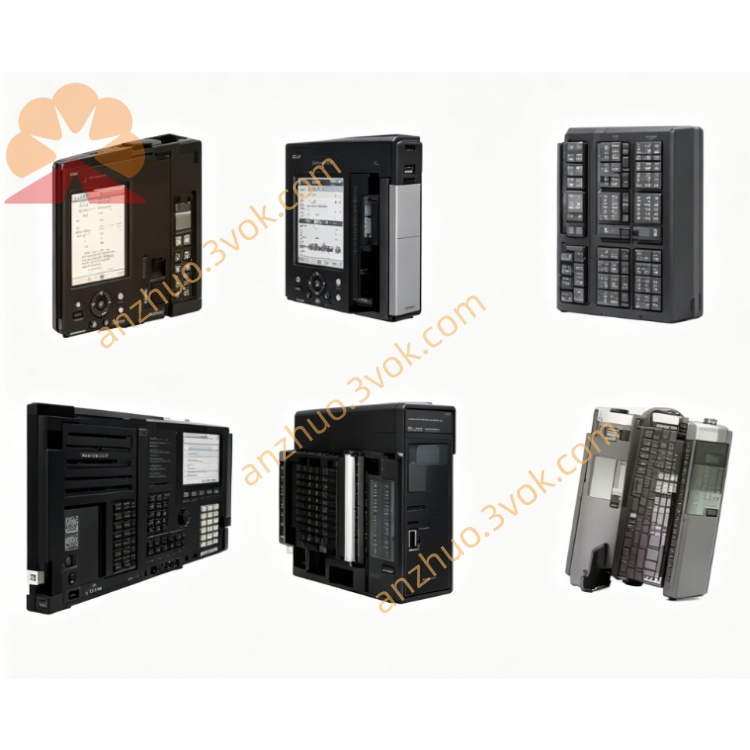
2) Panel Indicator Lights
CH01–CH16 (Green): Lit when corresponding relay engages
PWR (Green): 24VDC Power Supply Normal on Terminal Board
FUSE (Red): Lit when any channel fuse blows (Single Channel Position)
3) Comparison of the Same Series (9668 vs 9662)
9668-110: Enhanced RO Terminal Board (With Test Points + Diagnosis + High Current Relay)
9662-110: Standard RO Terminal Board (Basic Relay + Indicator Lights)
9662-610: 24VDC Active DO Terminal Board (No Relay, Transistor Output)
9662-810: 120VAC Relay Output Terminal Board (High Voltage AC)
II. Operating Instructions (Installation / Wiring / Maintenance)
1) Installation Configuration
32-Point RO Module (3636R/3637R): 1 Module paired with 2 9668-110 (1–16, 17–32 each 1 unit)
Installation Location: Cabinet DIN Rail, Close to Load Side, Shorten High Current Wiring
Hot Swap: Supports Online Replacement, Does Not Affect System Operation
2) Wiring Specifications (24VDC Load Circuit)
Power Side: 24VDC+ → PWR+; 24VDC‑ → PWR–
Load side: CHx (NO/COM) → Load; The other end of the load is connected to 24VDC -
Wire diameter: 1.5–2.5 mm² multi-strand copper wire, equipped with crimp terminals
Fuse: 3A slow-acting; The red light of FUSE turns on immediately, then power is cut off and the fuse is replaced
3) Fault handling
FUSE is on: Corresponding channel short circuit / overload → Replace the 3A fuse, check the insulation of the load
CH is not on: Check the module output, 24VDC power supply, relay status, load wiring
PWR is not on: Check the 24VDC power supply, flat cable connection, and the main fuse of the terminal board
Get a Quote