9662-1
Description
I. Product Overview (Core Parameters)
1) Basic Specifications
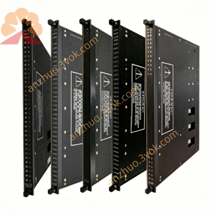
Model: 9662-1 (9662-110, Relay Output Termination Panel)
Signal Type: 24VDC Relay Output (Dry Contact)
Channel Count: 16 Points / Board; 32 Points RO Module requires 2 Terminal Boards
Load Voltage: Maximum 30VDC / 250VAC (Relay Contact Voltage Rating)
Contact Capacity: Each Path 3A @ 24VDC (Resistive Load)
Protection: Each Path 3A Slow-Melting Fuse, with Independent FUSE Red Light
Relay: Built-in 16-channel 24VDC Coil Relay, TMR Triple Redundancy
Isolation: ≥1500VAC Field - System Isolation
Common Terminal: Grouped Common Terminal for Facilitating Different Load Circuits Distribution
Safety Level: SIL3 (IEC 61508)
Operating Voltage: 24VDC ±10% (Coil Power Supply)
Temperature: -40℃ ~ +70℃
Certifications: CE, UL, CSA, ATEX/IECEx
Installation: 35mm DIN Rail
Compatible Modules: 3636R, 3637R (Tricon 32-Point Relay Output Module)
Connection Cable: Special Flat Cable (e.g. 9662-110 Matching Cable)
2) Panel Indicator Lights
CH01–CH16 (Green): Lit when corresponding relay engages
PWR (Green): Normal 24VDC Power Supply on Terminal Board
FUSE (Red): Lit when any channel fuse blows
3) Quick Overview of the Same Series (9662 Family)
9662-110: 24VDC, 16 Point Relay Output (Main Model)
9662-610: 115VAC, 16 Point Relay Output
9662-910: 120VDC, 16 Point Relay Output
II. Usage Instructions (Installation / Wiring / Maintenance)
1) Installation Configuration
32 Point RO Module (3636R/3637R): 1 Module paired with 2 9662-1 (1–16, 17–32)
Installation Location: Cabinet DIN Rail, Close to 24VDC Load Side
Hot Swap: Supports Online Replacement without Affecting System Operation
2) Wiring Specifications (24VDC Load Circuit)
Terminal Board Side: 24VDC+ → Common Terminal; CH+ → Load +; Load- → 24VDC-
Wire Diameter: 1.5–2.5 mm² Multi-strand Copper Wire
Fuse: 3A Slow-Melting; FUSE Red Light On Immediately Causes Power Off and Replacement
3) Fault Handling
FUSE Lit: Corresponding Channel Short Circuit / Overload → Replace 3A Fuse
CH Unlit: Check Module Output, 24VDC Power Supply, Relay Status, Load Wiring
PWR Unlit: Check 24VDC Power Supply, Flat Cable Connection, Terminal Board Fuse
Get a Quote