A06B-6047
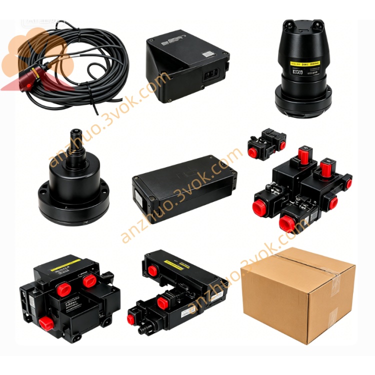
Description
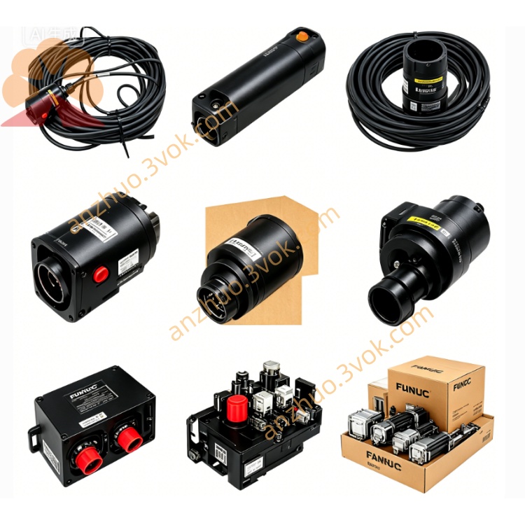
Main Technical Specifications
Series: M‑series DC servo drive (A06B‑6047‑H001/H002/H003/H004)
Input Voltage: Three‑phase AC 185V (50/60Hz)
Output Power: 1.5kW–3.7kW (model‑dependent)
Control Mode: Analog velocity command (0–10V) + tachometer feedback
Feedback: Incremental encoder (motor‑mounted)
Protection Class: IP20 (chassis‑mounted)
Cooling: Natural convection (air‑cooled)
Dimensions (H002/H003): 152mm × 457mm × 211mm
Weight: ~8kg
Operating Temperature: 0°C to +40°C
Storage Temperature: −20°C to +60°C (non‑condensing)
Humidity: ≤80% RH (non‑condensing)
Product Features
Precise Velocity Control: Closed‑loop analog control with tachometer feedback ensures stable speed regulation and low speed ripple.
Compact & Rugged: Chassis‑mounted design with heavy‑duty components for industrial environments.
Integrated Protection: Built‑in circuit breakers, overvoltage (HVAL), overcurrent (BRK), and excessive error alarms for fault protection.
Easy Integration: Analog interface compatible with FANUC System 6/10/11 CNC controllers; plug‑and‑play with 10M/20M/30M DC motors.
Proven Reliability: Classic M‑series design with long‑term durability for legacy machine tools.
Application Scope
Legacy CNC Machine Tools: CNC lathes, vertical milling machines, and small machining centers (X/Y/Z feed axes).
FANUC System Compatibility: System 6, System 10, System 11 CNC controllers.
DC Servo Motor Systems: Paired with FANUC 10M/20M/30M DC servo motors.
Retrofit Projects: Replacement or upgrade of aging DC servo systems in older machinery.
Installation Instructions
Mount the drive vertically on a rigid, flat metal panel to ensure proper cooling and minimize vibration.
Maintain 100mm clearance around all sides for airflow and wiring access.
Ensure the mounting surface is clean, flat, and free of conductive debris to prevent short circuits.
Secure the drive with four mounting bolts (M5/M6) tightened to 2.5–3.0N·m torque.
Avoid installation in direct sunlight, near heat sources, or in corrosive/explosive atmospheres.
Wiring Requirements
Power Wiring:
Disconnect all AC power before wiring to prevent electric shock.
Connect three‑phase AC 185V to terminals L1/L2/L3; ensure correct phase sequence.
Connect protective earth (PE) to the chassis ground terminal (ground resistance ≤4Ω).
Motor Wiring:
Connect DC servo motor armature to terminals M+/M−; match motor polarity.
Connect tachometer feedback wires to dedicated terminals (TACH+/TACH−).
Control Wiring:
Run analog command cable (0–10V) from CNC controller to drive’s velocity command terminals.
Separate control cables from power cables by ≥15cm to reduce electromagnetic interference.
Use shielded cables for encoder/feedback signals; ground shields at both ends.
Operation Guidelines
Power‑On Sequence:
Turn on CNC controller first; verify no alarms.
Enable servo power; check that BRK and HVAL LEDs are off.
Run no‑load test: check for abnormal noise, vibration, or overheating.
Operating Limits:
Do not exceed rated voltage, current, or continuous torque.
Avoid frequent start/stop cycles (>10 cycles/min) to prevent overheating.
Monitor drive temperature; keep case temperature <60°C during operation.
Alarm Handling:
BRK (Red): Overcurrent or short circuit → Check motor wiring, load, or drive IGBTs.
HVAL (Red): Overvoltage → Check input AC voltage or regenerative circuit.
EXCESS ERROR: Position following error → Check encoder, wiring, or mechanical load.
Maintenance Instructions
Monthly:
Disconnect power; clean dust/debris from drive vents and heat sinks with dry compressed air.
Check all wiring terminals for tightness; re‑torque loose screws.
Quarterly:
Inspect power cables, motor cables, and encoder cables for wear, cracking, or damage.
Verify operation of alarm LEDs and circuit breakers via test cycles.
Annually:
Check internal electrolytic capacitors for bulging or leakage (replace if degraded).
Test tachometer and encoder signal quality with a multimeter/oscilloscope.
Prohibitions:
Do not open the drive chassis or modify internal components (voids warranty).
Do not operate the drive with missing or damaged covers.
Safety Precautions
Only qualified electrical technicians may install, wire, or maintain the drive.
Disconnect all power and wait 5 minutes for internal capacitors to discharge before maintenance.
Never touch live terminals or internal components when power is applied.
Ensure reliable grounding to prevent electric shock and reduce noise interference.
Keep the drive and cables away from flammable materials and high‑temperature surfaces.
Do not use the drive if it shows physical damage, water ingress, or abnormal noise.
Get a Quote