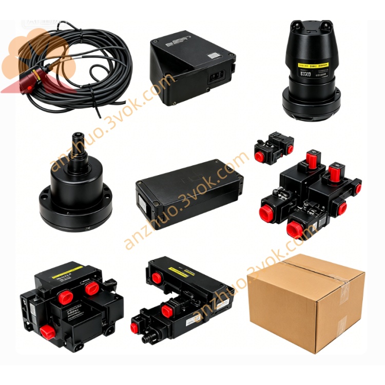
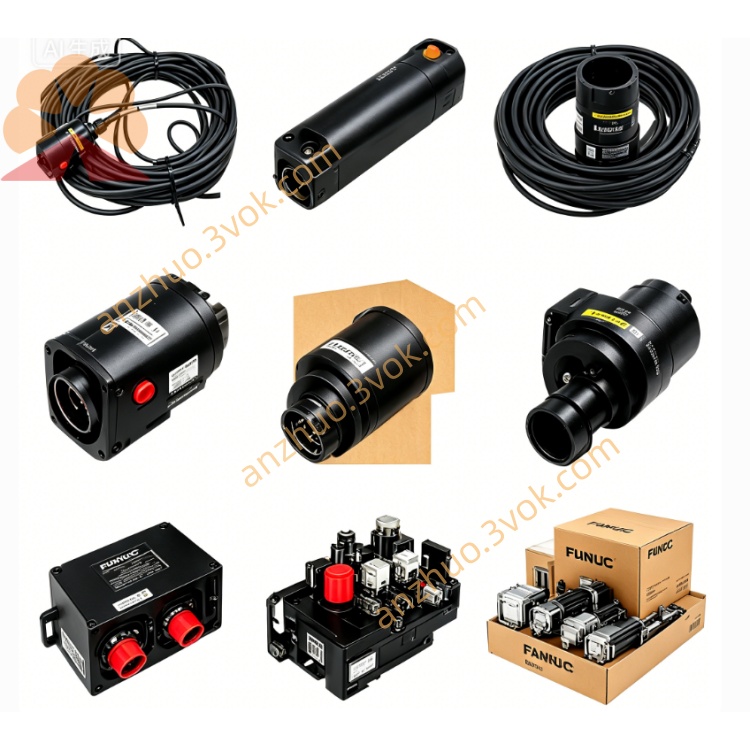
A06B-0371
Description
Main Technical Specifications
Series: α1 (Alpha 1/3000) compact AC servo motor
Model Variants: A06B-0371-B075 (no brake), A06B-0371-B175 (with brake), etc.
Rated Continuous Output Power: 0.3 kW
Rated Continuous Torque: 1.0 Nm; Maximum Torque: 3.0 Nm
Rated Speed: 3000 rpm; Maximum Speed: 3000 rpm
Rated Voltage: Three-phase 90 V AC (200 Hz)
Rated Current: 2.5 A; Peak Current: 5.5 A
Feedback Encoder: Built-in incremental encoder (2500 ppr, αi64)
Shaft: Tapered shaft (TPR) with keyway
Brake Option: With/without 24 V DC holding brake
Cooling: Natural convection (self-cooled)
Protection Class: IP65 (standard); IP67 (sealed variants)
Insulation Class: F (155 °C)
Rotor Inertia: 0.00021 kg·m²
Approximate Weight: 3.5 kg
Product Features
Compact & Lightweight: 3.5 kg mass and small frame reduce installation space and mechanical load, ideal for tight layouts.
High Torque Density: Delivers 1.0 Nm continuous torque at 3000 rpm, optimized for high-speed, light-to-medium load tasks.
Tapered Shaft Design: Tapered shaft with keyway ensures secure, zero-backlash coupling for precise motion transmission.
Optional Holding Brake: 24 V DC brake models maintain load position during power-off, preventing drift in vertical axes.
High-Resolution Encoder: 2500 ppr incremental encoder provides accurate position/speed feedback for consistent ±1 pulse positioning.
IP65/IP67 Protection: Sealed housing resists dust, coolant, and oil mist, ensuring reliability in harsh workshop environments.
Low Inertia Rotor: Enables fast acceleration/deceleration (0–3000 rpm in <10 ms) and smooth low-speed operation.
Wide Compatibility: Matches FANUC αiSV series 90V servo amplifiers and 0i‑C/D series CNC systems for plug-and-play integration.
Application Scope
CNC Machine Tools: Small CNC lathes, milling machines, and vertical machining centers for feed axes (X/Y/Z).
Industrial Robotics: Light-duty robot arms, SCARA robots, and gantry robots with compact joint requirements.
Automation Equipment: Packaging machinery, material handling systems, and assembly lines needing precise positioning.
Special Machinery: Laser markers, precision positioning stages, and automated testing equipment with limited space.
Installation Instructions
Mount the motor on a rigid, flat base to avoid resonance and shaft misalignment.
Keep the mounting flange clean, flat, and free of debris to ensure full contact.
Align the tapered shaft with the load; use a dedicated tapered coupling to prevent slippage.
Tighten flange bolts evenly to 2.8 Nm torque to avoid housing distortion.
Reserve 50 mm clearance around the motor for ventilation, encoder/brake wiring, and maintenance.
For brake models, ensure the brake is electrically connected and functional before applying load.
Wiring Requirements
Perform all wiring with power disconnected to avoid electric shock.
Use FANUC-approved power, encoder, brake, and ground cables (AWG18–20).
Connect three-phase power (U, V, W), protective earth (PE), and 24 V DC brake terminals (if equipped) securely.
Route encoder cables separately from power/brake cables (≥10 cm) to minimize EMI.
Follow FANUC’s official wiring diagram for correct encoder polarity and brake operation.
Torque all terminal screws to 1.2 Nm to prevent loose connections.
Working Environment
Operating Temperature: 0 °C to +40 °C
Storage Temperature: −20 °C to +60 °C (non-condensing)
Humidity: ≤80% RH (non-condensing)
Altitude: ≤1000 m (derate output 1% per 100 m above 1000 m)
Atmosphere: Free of corrosive gases, explosive dust, or excessive oil mist
Maintenance Instructions
Every 3 months: Disconnect power, clean dust/oil from housing and brake assembly with a dry cloth.
Every 6 months: Check mounting bolts, coupling tightness, encoder connectors, and brake wiring for security.
Every 12 months: Inspect bearings for abnormal noise/vibration; replace bearings if noise occurs.
Monthly (brake models): Test brake holding torque and release function under no-load conditions.
Quarterly: Use CNC diagnostic tools to verify encoder signal quality and position stability.
Do not disassemble the motor, encoder, or brake privately; unauthorized disassembly voids the warranty.
Safety Precautions
Only qualified personnel may install, wire, or maintain the motor and brake system.
Disconnect all power (main and brake) before maintenance; wait 5 minutes for capacitors to discharge.
Never touch the rotating shaft, live electrical components, or brake parts during operation.
Ensure reliable grounding (≤4 Ω) to prevent electric shock and reduce EMI.
Do not modify the motor’s internal structure, encoder configuration, or brake wiring arbitrarily.
The holding brake is for static holding only; do not use it for dynamic braking or emergency stops.
Get a Quote