CACR-SR15SZ1SD-Y21
1. Product Introduction
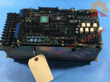
CACR-SR15SZ1SD-Y21 is a 1.5kW AC servo drive of the Yaskawa VS-800 series, featuring factory-customized parameters and I/O logic (identified by the -Y21 suffix). It is designed with high dynamic response and superior energy efficiency, integrating optimized hardware architecture and advanced algorithms to achieve precise adjustment of motor speed, torque and position, making it suitable for CNC machine tools, industrial automation equipment, and other scenarios requiring high-precision control. This servo drive offers stable performance, simple operation, and strong durability, adopting high-quality components and an optimized heat dissipation design to support continuous operation, which can significantly improve equipment efficiency and product quality in practical applications. Its rated output power is 1.5kW, with a 3-phase AC 200~230V, 50/60Hz input voltage, 11.4A (RMS) rated output current, and 54A peak output current (300% overload, maximum 3 seconds). It supports position pulse and analog speed control modes, is compatible with an incremental encoder (2500p/rev, 5V), has an IP20 protection grade, and is suitable for operating environments with 0~55°C (no condensation). The -Y21 suffix denotes a factory-specialized customized version, with fixed I/O logic, gain parameters, and motion sequences for specific equipment—standard models or other customized versions cannot replace it.
Description
1. Product Introduction
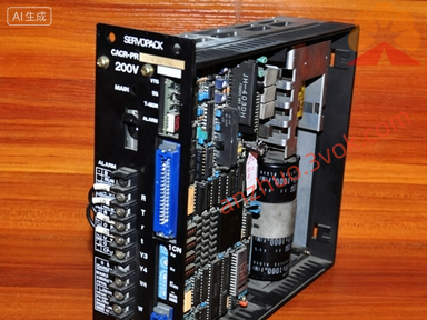
CACR-SR15SZ1SD-Y21 is a 1.5kW AC servo drive of the Yaskawa VS-800 series, featuring factory-customized parameters and I/O logic (identified by the -Y21 suffix). It is designed with high dynamic response and superior energy efficiency, integrating optimized hardware architecture and advanced algorithms to achieve precise adjustment of motor speed, torque and position, making it suitable for CNC machine tools, industrial automation equipment, and other scenarios requiring high-precision control. This servo drive offers stable performance, simple operation, and strong durability, adopting high-quality components and an optimized heat dissipation design to support continuous operation, which can significantly improve equipment efficiency and product quality in practical applications. Its rated output power is 1.5kW, with a 3-phase AC 200~230V, 50/60Hz input voltage, 11.4A (RMS) rated output current, and 54A peak output current (300% overload, maximum 3 seconds). It supports position pulse and analog speed control modes, is compatible with an incremental encoder (2500p/rev, 5V), has an IP20 protection grade, and is suitable for operating environments with 0~55°C (no condensation). The -Y21 suffix denotes a factory-specialized customized version, with fixed I/O logic, gain parameters, and motion sequences for specific equipment—standard models or other customized versions cannot replace it.
2. Installation & Wiring
2.1 Installation
Install the servo drive vertically in a control cabinet, leaving no less than 50mm clearance on all sides to ensure effective heat dissipation. The installation environment should be clean and dry, free from dust, oil fumes, corrosive gases, and excessive vibration to ensure stable operation of the equipment.
2.2 Simplified Wiring
Follow the correct sequence when wiring: first, connect the motor U/V/W and encoder cable to the CN2 interface, ensuring correct wiring to avoid signal loss or equipment damage; then, connect control signals (such as pulse and direction) to the CN1 interface, which uses -Y21 customized I/O logic (do not use standard I/O wiring diagrams); finally, connect the 3-phase power supply to the R/S/T terminals and reliably ground the drive, ensuring the ground resistance is no more than 10Ω. Note that power cables with a cross-sectional area of no less than 2.5mm² should be used for the main circuit, and shielded twisted-pair cables should be used for signal cables to reduce electromagnetic interference. Before formal operation, it is recommended to check the wiring point by point and conduct step-by-step debugging according to the debugging outline to ensure correct wiring and normal system operation. Do not drop wire ends or screws into the servo drive to avoid equipment damage.
3. Basic Operation
3.1 Panel Button Functions
The core buttons on the CACR-SR15SZ1SD-Y21 panel include MODE, SET, ↑/↓, and RUN/STOP. The MODE button switches between monitoring and fault modes; the SET button confirms operations and accesses related settings; the ↑/↓ buttons adjust parameter values or switch monitoring items; the RUN/STOP button starts or stops local jog operation. Most alarm and error issues can be initially resolved by resetting parameters, resetting the drive, or re-powering it, but complex faults should not be handled arbitrarily on-site and should be referred to professional technical support. The servo drive has eleven possible alarm code types (1-7, A, B, C, F), which can be referred to the detailed manual for further troubleshooting if needed.
3.2 Common Operations
For local jog operation: press the MODE button to select "JOG" mode, press SET to confirm, then use the ↑/↓ buttons to control the motor to jog forward or backward, and press STOP to end the operation. For monitoring: press the MODE button to switch and check real-time data such as motor speed, output current, and fault codes. For parameter operation: press the MODE button, enter the default password 0000, and press SET to access the parameter interface. Note that all parameters of the -Y21 customized version are factory-locked—they can only be viewed, not arbitrarily modified, to avoid equipment failure. After completing basic debugging, gradually conduct semi-automatic and automatic operation tests, observe multiple working cycles, and ensure the system operates continuously and correctly.
4. Common Faults & Solutions
When the servo drive malfunctions, a corresponding alarm code will be displayed on the panel. For alarm code A.10 (overcurrent): first power off the drive for 5 minutes, then check for motor short circuits, incorrect wiring, or excessive load, and restart the drive after troubleshooting. For alarm code A.31 (overvoltage): check if the input power voltage is too high and inspect the regenerative resistor for open circuits. For alarm code A.40 (overtemperature): clean the fan filter to ensure normal fan operation and reduce the load if necessary. For alarm code A.80 (encoder error): check if the encoder cable is broken or loosely connected, and reconnect or replace the cable if needed. Common alarm codes (such as A.10, A.31, and A.40) can be handled using the above methods; if the fault cannot be resolved, contact professional technical support to avoid secondary equipment damage from forced operation.
5. Safety & Maintenance
High voltage hazard: the drive’s terminals still carry high voltage for 5 minutes after power off—do not touch the terminals during this period to avoid electric shock. For daily maintenance: check the fan operation status and panel alarm information daily; clean the fan filter weekly to prevent dust blockage that affects heat dissipation; tighten terminal screws monthly to avoid loose connections, and do not loosen the fixed screws of the components, especially the screws with red marks. When replacing the drive, only use the same model (CACR-SR15SZ1SD-Y21)—do not use standard models or other customized versions, and do not arbitrarily modify the firmware or parameters to prevent equipment malfunction. This servo drive is widely used in industrial automation fields such as CNC machine tools and packaging equipment; proper installation, operation, and maintenance can effectively extend its service life. For hardware-related faults or advanced parameter settings, contact professional maintenance personnel instead of attempting on-site modifications.
Get a Quote