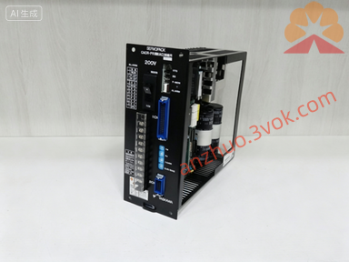
CACR-SR15SB1AF-Y78
Description
I. Model Interpretation
CACR‑SR: VS‑800 Series SERVOPACK
15: Rated power of 1.5kW
S: S-type housing (mounting hole positions are incompatible with BY/BZ/BE and other types)
B: 200V voltage class
1A: Standard control hardware
F: Custom I/O and parameter version
-Y78: Exclusive customized program (I/O, gain, electronic gear, homing / limit logic are all locked)
II. Hardware Technical Specifications (Consistent with Y100/Y160)
• Rated Power: 1.5kW
• Input: Three-phase AC200–230V, 50/60Hz
• Rated/Peak Current: 18A / 54A (300% Overload ≤3 seconds)
• Control Mode: Default Position Pulse (Y78 Customized)
• Encoder: Incremental 2500p/r, 5V Line Driver
• Cooling/Protection: Built-in Fan Forced Air Cooling, IP20
• Environment: 0–40℃, Humidity ≤80% RH (No Condensation), Altitude ≤1000m
• Weight: Approximately 9kg
III. - Y78 Customization Key Points (Critical Differences)
1. Dedicated I/O Definition: CN1 terminal functions (Emergency Stop, Positive/Negative Limit, Positioning Complete, Alarm Output, etc.) are completely incompatible with Y100/Y160 logic. Verify diagrams before wiring.
2. Full Parameter Locking: Electronic gear ratio, servo gain, acceleration/deceleration time, and zero return method are fixed customized values and cannot be modified; the general SR15 parameter list does not apply.
3. Fixed Motion Sequence: Power-on initialization, zero return process, and limit trigger logic are Y78-specific and cannot be directly replaced with other firmware models, as this will cause alarms, positioning failure, or non-operation.
4. Unique Replacement: When replacing due to failure, the same model CACR-SR15SB1AF-Y78 must be used.
IV. Installation and Wiring (Universal Specifications for the Series)
1. Installation: Vertical installation, with ≥50mm cooling clearance on both sides, and no obstruction to the bottom fan outlet.
2. Wiring Sequence: Connect motor U/V/W + Encoder CN2 first → Then connect control signals CN1 → Finally connect main power R/S/T + Ground (Ground resistance ≤10Ω).
3. Cables: Power cables ≥2.5mm², signal cables use shielded twisted pair, with the shield grounded at one end.
V. Panel Operation (Only Monitoring and Jogging, Parameters Unmodifiable)
• Buttons: MODE (Monitor / Parameter / Fault), SET (Confirm), ↑/↓ (Value Adjustment), RUN/STOP (Local Start/Stop)
• Parameter Mode: MODE → Password 0000 → SET (View Only, Modification Prohibited)
• Local Jogging (JOG): MODE → JOG → SET → ↑/↓ for Jogging (Default 500rpm)
VI. Common Alarms and Troubleshooting (Universal for the Series)
• A.10 Overcurrent: Motor short circuit, wiring error, or excessive load
• A.31 Overvoltage: Excessively high power supply voltage or open brake resistor
• A.40 Overheat: Blocked fan, poor cooling, or environment exceeding 40℃
• A.80 Encoder Fault: Cable disconnection, poor contact, or encoder damage
• Troubleshooting: Power off for 5 minutes → Check wiring/load → Restart; if alarm persists, contact the supplier.
VII. Safety and Maintenance
• High Voltage Hazard: Terminals remain high voltage for 5 minutes after power off; do not touch.
• Daily Maintenance: Check fan operation and panel alarms daily; clean fan filter weekly; tighten terminal screws and inspect cable aging monthly.
Get a Quote