
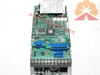
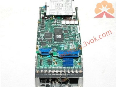
CACR-SR02BY1SG-E
Description
I. Model Meaning • CACR-SR: VS-800 Series SERVOPACK (discontinued in the old model) • 02: 0.2kW / 200W • B: B Series (digital + analog dual control) • Y: BY Shell (completely incompatible with AD/AY/AZ/BE) • 1SG: Control Firmware • ◦ 1: Standard Version • S: Pulse Position Control (command: pulse + direction) • G: Analog Speed Control (±10V) • -E: European Customized Version (English nameplate, European standard IO / parameters)
II. Rated / Electrical Parameters (Required) Table Project Parameter Input Power Three-phase AC 200 - 230V, 50/60Hz Control Power Single-phase AC 200 - 230V (internally derived from the main power supply) Rated Output Power 0.2kW (200W) Rated Output Current 2.2A Peak Current 6.6A (maximum for 3 seconds) Compatible Motor Yaskawa Old Model 0.2kW Incremental Encoder Motor (such as USAREM-02DE / USASEM-02A) Encoder Signal Incremental A/B/Z, Line Drive (5V) Cooling Method Natural Air Cooling (without fan) Dimensions (approx.) 182 × 135 × 88 mm (BY housing) Weight (approx.) 2.5 kg III. Control Modes (Focus on 1SG Firmware) 1. Position Control (Pulse Command) ◦ Command Form: Pulse + Direction (Single-ended / Differential optional) ◦ Input Frequency: Maximum 200kHz ◦ Electronic Gear: Parameter Setting (1/1 to 32767/1) 2. Speed Control (Analog Quantity) ◦ Command: ±10V → Corresponding Positive/Negative Rated Speed ◦ Input Impedance: Approximately 10kΩ ◦ Speed Loop: Built-in PI, Gain Adjustable 3. Mode Switching: Switch between Position/Speed Modes via External DI Signal (‑E Version IO Definition Fixed) IV. Terminal Wiring (Core) Main Circuit (Left Side) • R, S, T: Three-phase AC 200 - 230V Input • U, V, W: Servo Motor Output • Y3, Y4: External Regenerative Braking Resistor (200W: 20Ω/50W) • PE: Protection Grounding Control Interface CN1 (50-pin, -E European Version Definition) • DI (Input): Servo Enable, Positive/Negative Limit, Mode Switching, Alarm Reset, etc. • DO (Output): Servo Ready, Position Completion, Alarm, Zero Speed, etc. • Analog Quantity: SPD_REF (±10V), GND • Pulse Command: PULS, SIGN (Single-ended / Differential) Encoder Interface CN2 (20-pin) • Compatible Incremental Encoder: A, /A, B, /B, Z, /Z, 5V, GND V. Panel Operation (Digital Tube + 3 Keys) • MODE: Switch Display (Speed / Position / Current / Alarm) • UP/DOWN: Parameter Selection, Value Increase/Decrease • SET: Enter Parameter / Confirm Save Common Parameters (Factory Values, -E Version) • P00: Control Mode (0 = Position, 1 = Speed) → 0 • P01: Motor Type (Compatible 0.2kW) → 2 • P02: Encoder Resolution (2500p/rev) → 2500 • P03: Electronic Gear Fraction → 1 • P04: Electronic Gear Denominator → 1 • P05: Speed Loop Gain → 50 • P06: Speed Loop Integral Time → 20ms • P07: Position Loop Gain → 30 • P08: Acceleration/Deceleration Time → 100ms VI. Alarm Codes (Common, -E Version Same as Series) • 1: Overcurrent (Load Short Circuit / Motor Damage) • 2: Overvoltage (Power Supply Too High / Regeneration Abnormal) • 3: Undervoltage (Power Supply Phase Missing / Low Voltage) • 4: Overheating (Poor Heat Dissipation / Overload) • 5: Overload (Excessive Load / Stuck) • 6: Encoder Abnormality (Break Connection / Wiring Error) • 7: Limit Switch Trigger • A: Servo Not Ready • B: Parameter Error • C: Communication Abnormality • F: System Failure (Hardware Damage) VII. Installation and Usage Notes 1. Unique Shell: Only BY shell model can be used for replacement (AD/AY/AZ/BE pin positions and sizes are different) 2. -E Customization: Ordinary BY1SG cannot be directly substituted (IO definition, parameter lock are different) 3. Wiring: Power lines and signal lines are separated, encoder lines use twisted shielded cables 4. Grounding: PE must be reliably grounded to avoid interference 5. Load: Continuous load ≤ 100%, short-time peak ≤ 300% (≤ 3 seconds)
Get a Quote