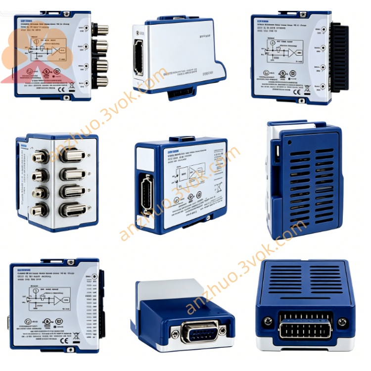
PCI-6561
Description
Model: PCI‑6561
Part Number: 778991‑01 / 02 / 03
Brand: National Instruments (NI)
Type: 100 MHz High-Speed Digital Waveform Generator / Analyzer (HSDIO)
Bus: Standard PCI (5 V, Half-Length Card)
Connector: 1×VHDCI‑68 Pin (High-Speed Differential)
Driver: NI‑HSDIO + NI‑DAQmx
Core Summary
PCI-6561 is a 100 MHz, 16-channel digital waveform instrument designed for high-speed digital testing, interface simulation, protocol verification, and semiconductor/ATE applications. It supports single-ended/differential, LVDS/LVTTL/LVCMOS levels, and can perform digital waveform generation + acquisition (bidirectional) simultaneously. It features large-capacity onboard memory and flexible trigger synchronization.
Main Specifications
Number of channels: 16 single-ended / 8 differential (LVDS/LVTTL programmable)
Maximum clock rate: 100 MHz (up to 200 Mb/s for DDR)
Data rate: SDR 100 Mb/s, DDR 200 Mb/s
Onboard memory: 1 Mbit / 8 Mbit / 64 Mbit per channel (depending on model)
I/O level: LVDS, LVTTL, LVCMOS (1.8 V / 2.5 V / 3.3 V)
Connector: VHDCI-68 (high-speed, impedance-matched)
Synchronization / Trigger: RTSI, external SMB clock/trigger, start/stop/reference trigger, pattern matching, change detection
Operating temperature: 0 ~ 55 °C
Power consumption: +5 V ≈ 1.2 A Typical application
High-speed Digital Interface Testing (LVDS, Parallel Bus)
Digital Protocol Simulation and Verification
Semiconductor / Chip Functional Testing (ATE)
High-speed Timing Logic Verification, Clock / Jitter Testing
Industrial Control, Communication Equipment Digital I/O Testing
PCI-6561 User Manual (Chinese Version - Simplified Operation)
I. Installation Steps
Power Off Installation: Shut down the PC, remove the power cord, insert the PCI-6561 into an idle 5 V PCI slot, and tighten the retaining screw.
Power On Recognition: After powering on, the system automatically detects the new hardware.
Driver Installation:
Install NI-HSDIO and NI-DAQmx (must be paired)
Open NI MAX (Measurement & Automation Explorer)
See PCI-6561 in "Devices and Interfaces", right-click for self-check, and if prompted "OK", it is normal.
II. Hardware Wiring (VHDCI-68)
Use NI Original High-Speed Cables such as SHC68-C68-D4 / D2 (recommended within 1 m to ensure signal integrity)
Pin Definitions:
16 single-ended DIO (D0 to D15)
8 pairs differential (LVDS)
Clock, Trigger, Ground, Power Supply
External Clock / Trigger: Connect through the SMB interface to a 100 MHz reference clock or trigger signal
III. Software Configuration (MAX / LabVIEW / C)
MAX Configuration
Select PCI-6561 → "Device Configuration"
Settings: Level Standard (LVDS/LVTTL), Channel Direction (Input / Output), Clock Source (Internal / External), Trigger Mode
LabVIEW Usage (Most Commonly Used)
Call HSDIO Waveform Generation / Acquisition VI
Configuration: Sampling Rate (≤100 MHz), Number of Channels, Memory Allocation, Trigger
Generation: Download digital patterns to onboard memory → Start Output
Acquisition: Start Sampling → Read Waveform Data → Analyze / Save
C Language (NI-DAQmx API)
Use DAQmxCreateTask / DAQmxCreateDOChan / DAQmxCreateDIChan
Configure Clock, Trigger, Memory, Write / Read Waveform Array
IV. Key Operating Points
Clock: Internal 100 MHz; External Clock requires LVCMOS 3.3 V or differential LVDS
Level Matching: Must be consistent with the level of the tested component (to avoid burning the input)
Memory Management: Long Waveforms Use Onboard Memory to Avoid PCI Bus Bandwidth Bottleneck
Signal Integrity: High-Speed (≥50 MHz) Must Use Impedance-Matched Cables, Length ≤ 2 m
Grounding: Equipment and Tested Component Share Ground to Reduce Noise
Electrostatic Protection: Discharge before Contacting the Board Card to Avoid Electrostatic Damage
V. Common Problems
Cannot Find Device: Check if the slot is 5 V PCI, if the driver is installed, and if MAX is refreshed
Self-Test Failure: Reinsert, Swap Slots, Update Driver
Unstable Signal / Error Code: Reduce Rate, Check Cable / Grounding, Confirm Level Matching
Trigger Not Working: Check Trigger Source, Polarity, Level, Connection
Get a Quote