MVME147-014A
Description
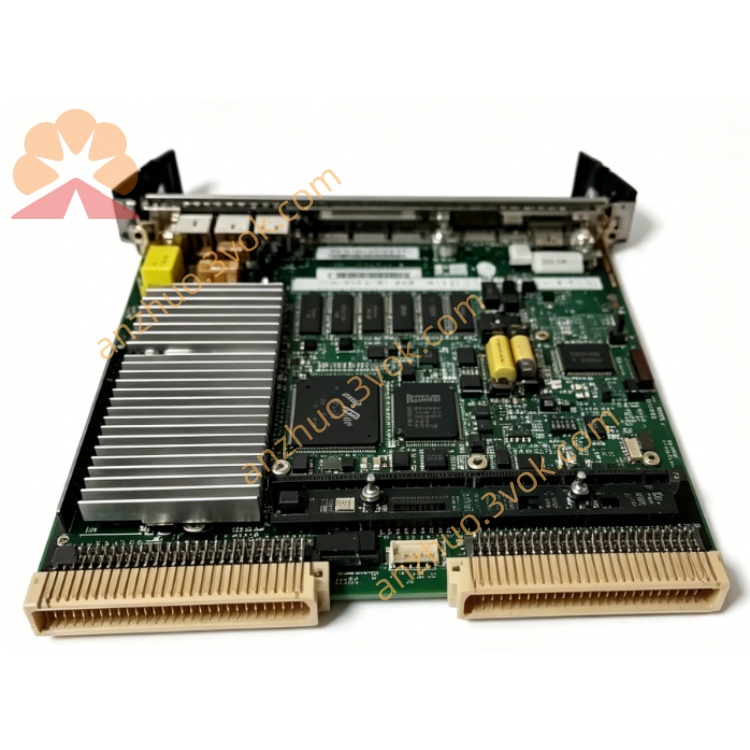
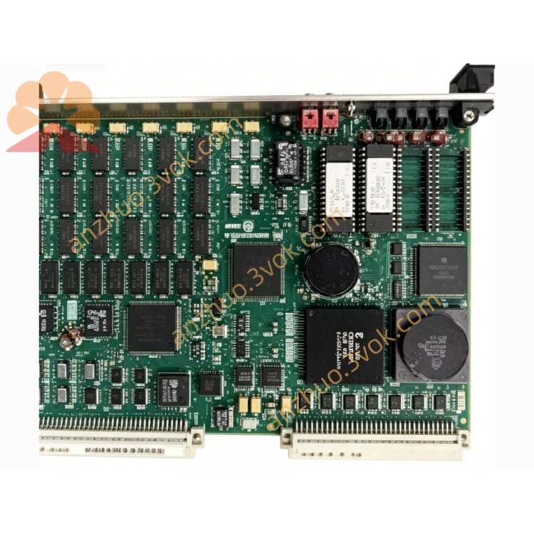
MVME147‑014A
6U VME64 Single Board Computer (SBC)
Official Datasheet (Plain Text, No Images)
1. General Description
2. Key Features
Processor: MC68030 @ 25 MHz, integrated MMU, 256‑byte instruction/data cache
Floating‑Point Coprocessor: MC68882 @ 25 MHz, IEEE 754 compliant
DRAM: 32 MB, programmable parity (error checking)
EPROM: 4 sockets, up to 4 MB total (16‑bit wide)
Battery‑Backed SRAM: 4 KB for data retention
Real‑Time Clock (RTC): Battery‑backed calendar/clock
Onboard I/O:
4 × EIA‑232‑D serial ports (Z8530)
1 × 8‑bit Centronics parallel port
1 × asynchronous SCSI (WD33C93, DMA capable)
1 × AUI 10 Mbps Ethernet
VMEbus Interface:
Address: A16/A24/A32
Data: D08/D16/D32
Master/slave mode, system controller function
Timers & Watchdog: Dual 16‑bit periodic timers, watchdog timer
Status LEDs: SCON, RUN, FAIL, STATUS
Switches: RESET, ABORT
3. Electrical Specifications
Power Supply: +5 VDC, ±12 VDC
Logic Levels: 5 V TTL compatible
VME Standard: ANSI/VITA 1‑1994, VME64 (IEEE 1014)
4. Mechanical Specifications
Form Factor: 6U VME
Dimensions: 233.4 mm × 160 mm
Mounting: Standard VME chassis slot
5. Environmental Specifications
Operating Temperature: 0 °C to +55 °C
Storage Temperature: −20 °C to +70 °C
Relative Humidity: 5%–95% RH, non‑condensing
6. Supported Operating Systems
VxWorks
Motorola VERSAdos
NetBSD/mvme68k
Custom embedded RTOS
Bare‑metal programs
7. MVME147‑014 vs 014A (Difference Only)
MVME147‑014: Initial PCB / component revision
MVME147‑014A: Rev A (hardware update, minor early issues fixed; 100% compatible in function, pinout, and electricals)
Software, configuration, cabling, and chassis: fully interchangeable
8. MVME147 25 MHz Series Overview (Including “A” Revisions)
MVME147‑011: 25 MHz, 4 MB, ETH+SCSI
MVME147‑011A: 25 MHz, 4 MB, ETH+SCSI (Rev A)
MVME147‑012: 25 MHz, 8 MB, ETH+SCSI
MVME147‑012A: 25 MHz, 8 MB, ETH+SCSI (Rev A)
MVME147‑013: 25 MHz, 16 MB, ETH+SCSI+parity
MVME147‑013A: 25 MHz, 16 MB, ETH+SCSI+parity (Rev A)
MVME147‑014: 25 MHz, 32 MB, ETH+SCSI+parity (top memory)
MVME147‑014A: 25 MHz, 32 MB, ETH+SCSI+parity (Rev A, latest)
Get a Quote