KRC1
Description
2. Technical Specifications
Model: KRC1 (KR C1)
Controller Type: PC-based, open architecture
Compatible Robots: KR15, KR30, KR45, KR60, etc. (6-axis)
System Software: KSS V4.x (Windows 95)
Power Supply: 3×400/415/440/480/500/550 V AC, 50/60 Hz, 25 A
Standard Interfaces: CAN/DeviceNet, Ethernet, RS-232
Optional Fieldbuses: INTERBUS-S, FIPIO
Drives: Integrated servo drives for axes 1–6
Teach Pendant: KCP1 (8.4” TFT, 6D joystick)
Protection Class: IP20 (cabinet), IP65 (KCP1 front)
Operating Temp: 0°C to +45°C
Storage Temp: -20°C to +60°C
Dimensions (W×H×D): Approx. 600×800×300 mm
Weight: Approx. 80 kg
3. Main Components & Controls
3.1 Control Cabinet
Main Power Switch: 3-phase AC input ON/OFF.
Emergency Stop (E-Stop): Red mushroom button; cuts power to servo drives.
Reset Button: Clears faults and restarts system.
Status LEDs: Power, Run, Error, Servo Ready.
Drives Module: Amplifiers for axes 1–6.
I/O Module: Digital/analog inputs/outputs (24 V DC).
Fieldbus Slots: CAN/DeviceNet, Ethernet, optional INTERBUS-S.
Floppy/CD-ROM: For program backup/restore.
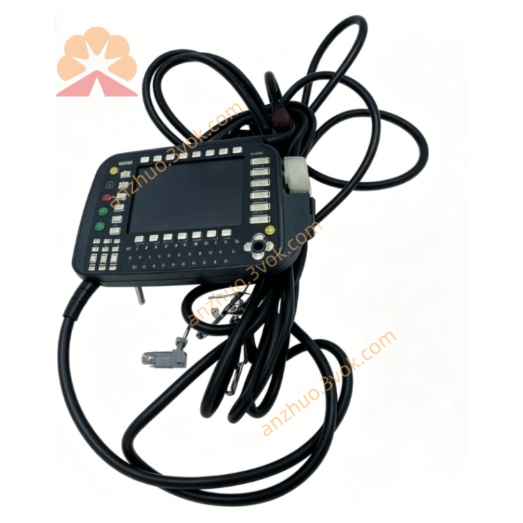
3.2 Teach Pendant (KCP1)
8.4” TFT Color Display: 640×480 resolution.
6D Joystick: Cartesian/axis jogging.
3-Position Enabling Switch (Rear):
0: Disabled
1: Enabled (manual jog)
2: Disabled
Mode Switch: T1 (≤250 mm/s), T2 (high speed), AUT (automatic), EXT (external).
Alphanumeric Keypad: Program editing, data input.
Function Keys: Menu navigation, command selection.
4. Safety Instructions
E-Stop: Use only in emergencies; stops all servo motion.
Enabling Switch: Must be held in Position 1 for manual jog; robot stops if released.
Mode Rules:
T1: Low speed for teaching/testing.
T2: High speed; clear workspace.
AUT: No personnel in workspace.
EXT: External PLC control; safety interlocks required.
No Modification: Never bypass safety circuits (E-Stop, enabling switch).
Work Envelope: Stay clear of robot’s full range of motion.
5. Installation & Connection
Positioning: Place cabinet on flat, level floor; allow 100 mm clearance for ventilation.
Power Connection: Connect 3-phase AC to X1; ensure correct voltage (400 V AC standard).
Motor Cables: Connect axes 1–6 motors to X20.
KCP1 Connection: Connect KCP1 cable to KCP port; tighten connector.
Fieldbus Setup: Install CAN/DeviceNet/Ethernet cables; configure addresses.
I/O Wiring: Connect 24 V DC I/O to terminal blocks; check polarity.
Grounding: Earth cabinet and robot base per local codes.
6. Operating Instructions
6.1 Power-Up
Turn main power switch ON.
System boots Windows 95 and KSS V4.x.
Check LEDs: Power ON, Run blinking, Error OFF.
Press Reset to clear faults.
Switch to T1 mode; hold enabling switch (Position 1).
Jog robot to verify motion.
6.2 Manual Jogging (T1/T2)
Mode: T1 (low speed) or T2 (high speed).
Hold enabling switch in Position 1.
Joystick:
Axis Mode: Move individual joints (A1–A6).
Cartesian Mode: Move TCP in X/Y/Z; rotate A/B/C.
Adjust speed with HOV keys (0–100%).
6.3 Programming (T1)
T1 mode; enable switch held.
Jog to desired position; press Record to store.
Add commands:
PTP(point-to-point),LIN(linear),CIRC(circular),WAIT,IF,FOR.Name program; save to hard disk or floppy.
6.4 Automatic Operation (AUT)
Select program from list.
Mode: AUT.
Clear workspace; close safety doors.
Press Start on KCP1 or external panel.
Press Stop to pause; E-Stop for emergency.
6.5 External Operation (EXT)
Connect external PLC via fieldbus (CAN/DeviceNet/Ethernet).
Configure I/O signals for Start/Stop, Fault Reset, Program Select.
Mode: EXT; ensure safety interlocks are closed.
Control robot via PLC commands.
7. Maintenance
Daily: Check E-Stop function; inspect cables for damage.
Weekly: Clean cabinet filters; verify fan operation.
Monthly: Check servo drive temperatures; tighten connectors.
Quarterly: Backup programs to floppy/CD; test restore.
Annual: Replace battery (CMOS/encoder); calibrate KCP1 touchscreen.
Environment: Keep cabinet dry; avoid dust and vibration.
Get a Quote