DF9201893-A0 Product Technical Manual
Description
DF9201893-A0 Product Technical Manual
Manufacturer: Yaskawa / Motoman
Model: DF9201893-A0
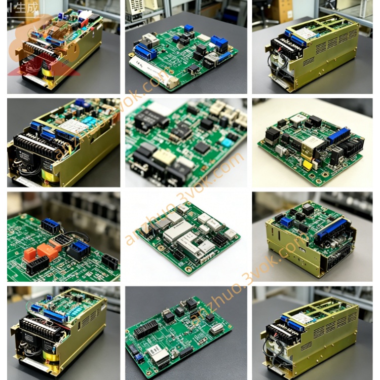
Board Alias: JANCD-MSV01B
Product Type: Robot Controller - Multi-axis Servo Control Board / Motion Control Card
Compatible System: Motoman DX200 Controller
I. Product Overview
DF9201893-A0 (JANCD-MSV01B) is a dedicated servo control board for Aichi Electric's DX200 controller. It is the basic standard version (A0 revision).
The core functions include servo drive for the robot body, synchronous motion control for external additional axes (transformation machines, walking axes, flipping tables), integrated multi-axis servo calculation, encoder feedback processing, high-speed interpolation, and signal isolation. It is suitable for standard automated production lines such as welding, handling, and assembly.
II. Versions and Compatibility
1. Version Differentiation
DF9201893-A0: Basic Standard Version (Non-Safety Type)
DF9201893-A0N: Safety Enhanced Version (SIL2/PLd Dual-Channel Safety Loop)
DF9201893-B0: Hardware Iterative Improvement Version (Performance and Compatibility Optimization)
2. Compatibility
Full Compatibility: DX200 Controller
Replacement Relationship
A0N can be substituted for A0 (Safety Function Compatible)
A0 cannot be substituted for A0N (Lacks Safety Redundancy)
B0 can directly replace A0 (Full Hardware/Software Compatibility)
Incompatible: DX100, NX100, YRC1000 (Different Bus Architecture)
III. Physical Specifications
Board Type: Standard 6U VME Industrial Card
Size: Approximately 300×160×20mm
Weight: Approximately 0.7kg
Core Chips: Motion Control ASIC, FPGA, 16-bit High-Speed ADC/DAC
Interface Configuration
CN1~CN4: Servo Encoder Feedback (Incremental / Absolute Value A/B/Z Differential)
CN5~CN8: Servo Drive Command Output (±10V Analog / Pulse Direction)
CN9: General I/O (Limit, Origin, Enable, Safety Signal)
CN10: VME Backplane Bus Interface
CN11: External Axis Expansion Communication
LED Indicators: PWR (Power), RUN (Operation), ALM (Fault), COM (Communication), AX1~AX4 (Axis Activation)
Process: 8-Layer PCB, Gold Plating, Industrial Grade Wide Temperature, Anti-Water Penetrating Coating
IV. Core Functional Characteristics
1. Multi-axis Servo Control
Number of controlled axes: 4-axis synchronous servo control
Control mode
Speed control: ±10V analog quantity (16-bit resolution)
Position control: pulse/direction (up to 4Mpps)
Torque control, electronic gear synchronization, follow interpolation
Control accuracy
Position loop refresh cycle: 0.5ms
Command linearity: ±0.05%
Encoder feedback: supports incremental/absolute values, long-distance drive (up to 80m)
2. Signals and Isolation
Differential encoder signal reception (A/B/Z, UVW)
All I/O, analog quantity ports 2500VAC optically isolated
Strong EMC anti-interference design, suitable for welding, frequency converter complex environments
3. Diagnosis and Status
Power-on self-detection, hardware fault diagnosis
LED status intuitive display
PWR: constantly on = normal power supply
RUN: flashing = normal operation
ALM: constantly on = hardware fault
COM: flashing = normal bus communication
AX1~AX4: constantly on = corresponding axis activated
Fault code storage, teach pendant readable
V. Electrical Parameters
Power supply: VME backplane 5VDC ±5%
Board power consumption: approximately 14W
Analog output: ±10V / ±10mA
Operating temperature: 0℃~+55℃
Storage temperature: -40℃~+85℃
Humidity: 5%~95% RH (no condensation)
Vibration: 10~500Hz / 1.5G
Impact: 15G / 11ms
VI. Installation and Application
Installation key points
Install on the VME expansion slot of the DX200 controller
Separate safety signal lines and power lines, spacing ≥ 100mm
Replace the same model board without hardware jumpers, just check the axis parameters
After installation, zero-point calibration and limit test must be performed Typical application
4-axis robot body servo control
External axis expansion: simultaneous linkage of transfer machine, walking axis, and flipping table
Automated lines for automotive welding, stamping, handling, and assembly
Multi-axis coordinated movement of standard automated workstations
Get a Quote