DF9201012-C0 Product Technical Manual
Description
DF9201012-C0 Product Technical Manual
Manufacturer: Yaskawa Motor (Yaskawa / Motoman)
Model: DF9201012-C0
Board Code: JANCD-MEW02-1 (REV.C0)
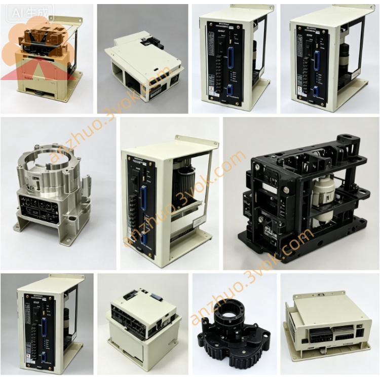
Product Type: Robot Controller - Servo Add-On Axis Board
Applicable Systems: Yaskawa Motoman XRC, NX100 Series Robot Controllers
I. Product Overview
DF9201012-C0 (JANCD-MEW02-1) is an additional axis servo control board specifically designed by ABB for Motoman industrial robots. It is mainly used to expand the robot system, control external servo axes (such as transfer machines, flipping tables, walking axes, external manipulators), and achieve synchronous linkage, coordinated movement, and precise positioning between the robot and external equipment. It is widely used in welding, handling, assembly, cutting, etc. in automated production lines. C0 is a high-performance hardware revision.
II. Physical Specifications
Board Type: Standard industrial control board (not VME standard)
Size: Approximately 160mm × 100mm × 20mm
Weight: Approximately 0.3kg
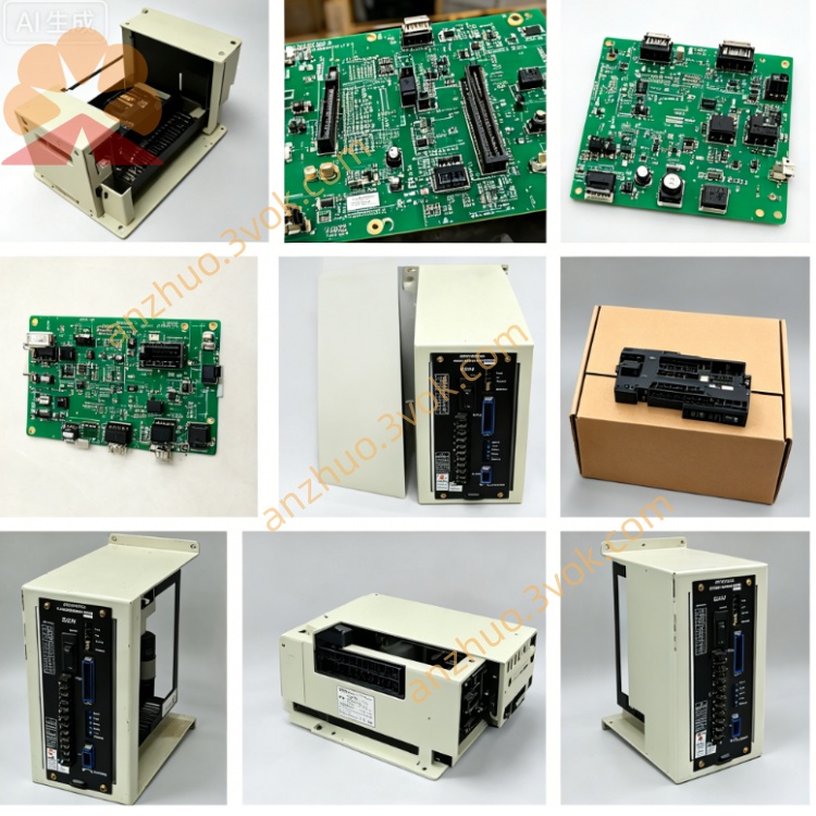
Core Components
Specialized servo control ASIC
Photoelectric isolation signal processing circuit
2-channel 12-bit D/A conversion module
Encoder feedback signal processing unit
External Interfaces
CN1: Servo drive analog quantity instruction output (±10V)
CN2: Encoder A/B/Z phase feedback input (differential signal)
CN3: Axis I/O terminals (limit, origin, enable, alarm)
CN4: Controller internal bus interface
LED Status Lights: PWR, RUN, ALM
Process Characteristics
6-layer industrial PCB, gold plating process
Whole board three protection coating (dust-proof, moisture-proof, salt fog-proof)
Industrial-grade components (-25℃~+75℃)
EMC Level 3 anti-interference
Port ESD static protection (±15kV)
III. Version and Compatibility
Version Evolution
DF9201012-C0 (JANCD-MEW02-1 REV.C0): Standard production version (currently the main promotion)
DF9201012-B0: Early basic version (lower performance, discontinued)
DF9201012-C02: C0 minor optimization version (electrical parameters slightly adjusted)
Applicable Systems
Fully compatible: Motoman XRC, NX100 robot controller
Partially compatible: Some Yasnac CNC systems (requires firmware adaptation)
Incompatible: DX100/DX200/YRC1000 new robot controllers (different bus architecture)
Replacement Relationship
C0 can directly replace B0, with fully downward compatibility in function
Not interchangeable with the robot body axis control board (such as JANCD-FC series)
IV. Core Functional Characteristics
1. Axis Control Capability
Number of Controlled Axes: Single-axis servo control (1-channel additional axis)
Control Modes
Speed Control (analog quantity ±10V output)
Position Control (pulse instruction output, optional)
Torque Control (analog quantity instruction)
Electronic Gear Synchronization (following the main motion of the robot)
Control Precision
Analog Quantity Output Resolution: 12 bits
Instruction Precision: ±0.1%
Position Loop Refresh: 1ms
Maximum Pulse Output: 2Mpps (optional configuration)
2. Feedback Processing
Encoder Type
Incremental A/B/Z (1Vpp differential)
Pulse Encoder (open collector)
Feedback Resolution: Up to 16 bits
Diagnostic Function: Real-time encoder break, short circuit, phase error diagnosis
3. Motion Control Function
Synchronous Linkage: Real-time coordinated movement with robot's 6 axes
Interpolation Function: Supports robot and external axes linear/arc interpolation
Motion Characteristics
Electronic Gear Ratio (1:0.001~1:1000)
S-shaped Curve Acceleration and Deceleration Smooth Control
Position/Speed Dual Closed-loop Regulation
Soft Limit, Position Out-of-Range Protection
4. I/O and Protection
Axis I/O
Positive/Negative Limit Switch Input (NPN/PNP)
Origin/Reference Point Switch Input
Servo enable output
Servo alarm input
Emergency stop interlock
Protection function
Overcurrent, overload, overvoltage protection
Position deviation, tracking error alarm
Over-speed, over-range protection
Power supply monitoring, open-circuit detection
5. Diagnosis and Maintenance
Real-time diagnosis: axis status, servo faults, feedback abnormalities
Fault log: Stores 200+ fault records (timestamp + code)
LED indication:直观 display of power, operation, alarm status
Firmware upgrade: Supports online upgrade of controller bus
V. Electrical Parameters
Working power supply
Input: 24VDC ±10% (powered by the controller internally)
Power consumption: Approximately 5W
Analog output
Signal: ±10V (speed command)
Drive capability: ±10mA
Resolution: 12 bits Environmental parameters
Operating temperature: 0°C ~ +60°C
Storage temperature: -40°C ~ +85°C
Humidity: 5%~95% RH (no condensation)
Vibration: 10~500Hz, 1.5G
Impact: 15G, 11ms
VI. LED Status Indicators
PWR (green): Normal 24V power supply (constant on)
RUN (green): System running (1Hz flashing)
ALM (red): Fault alarm (constant on = hardware failure, flashing = axis failure)
VII. Installation and Configuration
Installation: Insert into the XRC/NX100 controller expansion slot
Hardware Settings
No hardware jumpers, all parameters set by software
Software Configuration
Controller → Additional Axis Parameters → Control Mode, Gear Ratio, Limit Switches
Servo Gain, Acceleration and Deceleration, Origin Reset Method Debugging
Servo enable → Origin reset → Single-axis jog → Linkage test
Verification: RUN flashes, no alarm, smooth movement, precise synchronization
VIII. Typical Applications
Robot transfer machine - Rotation axis control
Robot walking axis - Servo drive control
Welding flipping table - Synchronous rotation control
Packing / Assembly - External auxiliary axis control
Cutting / Painting - Multi-axis linkage expansion
Automated production line - Robot + external axis collaborative control
Get a Quote