DF9200956-C0 Product Technical Manual
Description
DF9200956-C0 Product Technical Manual
Manufacturer: Yaskawa Electric
Model: DF9200956-C0
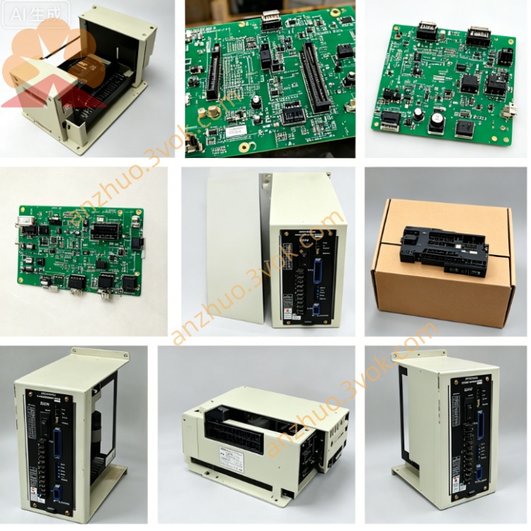
Board Code: JANCD-FC260-1
Product Type: CNC Control System - 4-axis Servo Motion Control Board
Applicable Systems: Yaskawa Yasnac i80, i90, MRC, MX3 Series CNC Controllers
I. Product Overview
DF9200956-C0 (JANCD-FC260-1) is a 4-axis synchronous servo control core board specifically designed by ABB for high-performance CNC machine tools and machining centers. It is mainly responsible for 4-axis servo closed-loop control, high-precision position feedback, high-speed pulse output, and multi-axis linkage interpolation calculation. It is a key hardware module for achieving complex trajectory processing and high-speed, high-precision motion control. C0 is a high-performance production revision, which has improved the computing speed and stability compared to the earlier version.
II. Physical Specifications
Board Type: Standard 6U VME industrial plug-in card
Dimensions: 233mm × 160mm × 20mm
Weight: Approximately 0.75kg
Core Components
32-bit motion control dedicated DSP
Multi-axis linkage ASIC chip
128MB high-speed cache
4-axis independent servo drive circuit
Photo-isolated signal processing unit
External Interfaces
CN1: Servo pulse / direction output for axes 1-2
CN2: Servo pulse / direction output for axes 3-4
CN3: Differential feedback input for 4-axis encoder A/B/Z
CN4: Axis limit / origin / emergency stop I/O terminals (4-axis independent)
CN5: VME backplane bus interface
LED Status Lights: PWR, RUN, AX1~AX4, ALM, BUS
Process Characteristics
8-layer industrial PCB, gold plating process
Whole board three-proof coating (dust-proof, moisture-proof, salt fog-proof)
Industrial-grade wide-temperature components (-25℃~+75℃)
EMC level 4 anti-interference, port ESD protection (±15kV)
III. Version and Compatibility
Version Evolution
DF9200956-C0 (JANCD-FC260-1): 4-axis standard high-performance version (currently the main promotion)
DF9200956-B0: Early basic version (lower performance, discontinued)
DF9200956-C1: C0 upgrade version (enhanced anti-interference, partial parameter optimization)
Applicable Systems
Fully compatible: Yasnac i80, i90, MRC, MX3, MPS-6000 series
Partially compatible: ABB robot controller external axis expansion (requires firmware adaptation)
Incompatible: DX100/DX200 robot systems (different bus architecture)
Replacement Relationship
C0 can directly replace B0, with complete downward compatibility in function
Not interchangeable with 2-axis control board (DF9200952-B0) (different number of axes, hardware architecture)
IV. Core Function Characteristics
1. Axis Control Capability
Control Axes: 4-axis independent / synchronous control (X/Y/Z/A or 4-axis linkage)
Control Modes
Position Control (pulses / direction)
Speed Control (analog / bus)
Torque Control
Electronic gear / electronic cam / electronic handwheel
Control Precision
Instruction Resolution: 0.0001mm (nanometer level)
Position Loop Refresh: 125µs
Interpolation Cycle: 0.5ms
Maximum Pulse Output: 8Mpps (per axis)
2. Feedback Processing
Encoder Type
Incremental A/B/Z (1Vpp differential)
Absolute encoder (SSI/BiSS)
Grating ruler / magnetic ruler (high-precision closed-loop)
Feedback Resolution: Up to 24 bits
Diagnostic Function: Real-time encoder break, short circuit, phase error diagnosis
3. Motion Control Function
Interpolation Mode
Linear interpolation (4-axis linkage)
Circular interpolation (2-axis / 3-axis)
Helical interpolation
NURBS spline interpolation (high-precision surface)
Motion Characteristics
Forward preprocessing (64 segments)
S-curve acceleration and deceleration smooth control Position loop / speed loop / current loop three closed-loop regulation
Axis synchronization, following, superposition, electronic gear ratio dynamic adjustment
4. I/O and protection
Axis I/O (4 independent axes)
Positive/negative limit switches
Origin/Reference point switches
Servo enable / alarm
Emergency stop interlock, overtravel protection
Protection functions
Overcurrent, overload, overvoltage, undervoltage protection
Position deviation, following error over-limit alarm
Over-speed, over-travel, overheating protection
Power supply monitoring, open circuit detection, fault self-locking
5. Diagnosis and maintenance
Real-time diagnosis: 4-axis status, servo fault, feedback abnormality, bus communication
Fault log: Store 1000 + fault records (timestamp + code + data)
LED indication: Intuitive display of power, operation, axis activation, alarm, bus status
Firmware upgrade: Support CF card / bus online upgrade, no need to replace hardware
V. Electrical parameters
Working power supply
Input: 5VDC ±5% (VME backplane power supply)
Power consumption: Approximately 15W Environmental parameters
Operating temperature: 0°C ~ +60°C
Storage temperature: -40°C ~ +85°C
Humidity: 5%~95% RH (no condensation)
Vibration: 10~500Hz, 2G
Impact: 20G, 11ms
VI. LED Status Indicators
PWR (green): Normal 5V power supply (always on)
RUN (green): System running (1Hz flashing)
AX1~AX4 (green): Corresponding axis activated (always on)
ALM (red): Fault alarm (always on = hardware failure, flashing = axis failure)
BUS (yellow): VME bus communication active (flashing)
VII. Installation and Configuration
Installation: Power off and insert into the VME expansion slot of the CNC controller
Hardware Settings
Axis address / node ID: Set by software, no hardware jumpers
Software Configuration
System → Axis Parameters → Control Mode, Resolution, Gain
Feedback type, limit logic, acceleration/deceleration parameters, electronic gear ratio Debugging
Servo enable → Origin reset → Single-axis jog → 4-axis联动 test
Verification: RUN flashes, AX is constantly on, no alarm, smooth movement, accuracy meets standards
VIII. Typical Applications
CNC machining center 4-axis联动 high-precision trajectory control
CNC lathes / grinders feed axis + spindle synchronous control
Electrical discharge machine (EDM) / wire cutting machine 4-axis precise motion control
CNC milling machines / drilling machines multi-axis positioning, compound processing
Automated special machines / robot changeover machines 4-axis external axis expansion control
Semiconductor / LCD equipment nanometer-level high-precision positioning control
Get a Quote