DF9200720-C1 Product Technical Manual
Description
DF9200720-C1 Product Technical Manual
Manufacturer: Yaskawa
Model: DF9200720-C1
Board Code: JANCD-MMM02-1E
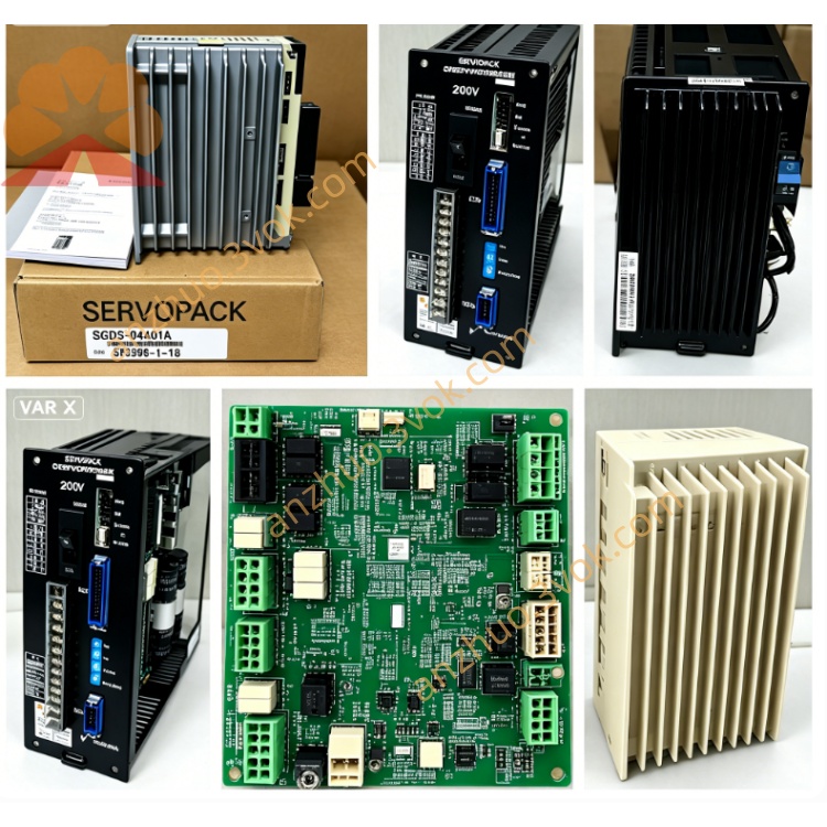
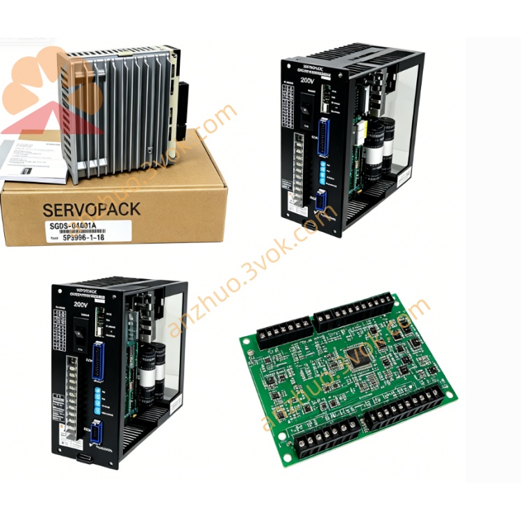
Type: Robot Controller - Motion Control Expansion Module (Multi-axis Servo Control Board)
Applicable Systems: Yaskawa Motoman DX200, DX100 Robot Controllers
I. Product Overview
DF9200720-C1 is a multi-axis motion control expansion board specifically designed for Yaskawa robot controllers. It is mainly used for external axis servo drive control (such as transfer machines, reversing transfer machines, walking axes, additional axes), supporting multi-axis synchronous interpolation, position closed-loop control, speed and torque control. It is the key hardware for achieving 7-12-axis expansion in the DX200 system. C1 is the first generation mass-produced stable version, with mature hardware and strong compatibility.
II. Physical Specifications
Board Type: Standard 6U VME Industrial Card
Size: Approximately 233mm × 160mm × 20mm
Weight: Approximately 0.68kg Interface
VME system bus interface (for communication with the controller backplane)
CN1: External axis servo encoder feedback interface (differential signal)
CN2: Servo drive control signal (pulse/direction, enable, alarm)
CN3: I/O signals for axis limit, origin, emergency stop, etc.
LED status lights: PWR, RUN, AX1~AX4, ALM, COM
Process
8-layer industrial PCB, gold plating process
Full board three-proof coating (dust-proof, moisture-proof, corrosion-proof)
Wide temperature industrial-grade components (-40℃~+85℃)
Seismic reinforcement design
III. Version and Compatibility
Version evolution
DF9200720-C1: JANCD-MMM02-1E (first stable version, 4-axis control)
DF9200720-C2: JANCD-MMM02-2E (upgraded optimized version, compatible with C1)
Applicable controllers
DX200: Fully compatible (standardly supported)
DX100: Requires firmware upgrade (partially compatible)
YRC1000: Incompatible (different hardware architecture)
Replacement relationship
C1 ↔ C2: Hardware fully compatible, can be directly interchanged
C1 as the basic version, C2 optimized stability and anti-interference
IV. Core Functional Characteristics
1. Axis control capability
Control axis number: 4 external servo axes (single C1 block)
Maximum expansion: One controller can install 2 C1 blocks → a total of 8 external axes
Control mode
Position control (pulse string output)
Speed control (analog quantity / bus)
Torque control
Synchronous interpolation (linked with the 6 axes of the machine body)
Encoder feedback
Supports incremental encoders (ABZ phase)
Supports absolute encoders (serial communication)
Resolution: Maximum 16MHz pulse input
2. Motion control performance
Control cycle: 1ms (synchronized with the robot control cycle)
Positioning accuracy: ±1 pulse (closed-loop control)
Speed range: 0~10MHz pulse output
Synchronization capability: 6 axes of the body + 4 external axes of 10 axes synchronous interpolation
Limit protection: hardware soft limit, hard limit, origin return, overtravel alarm
3. I/O and signals
Each axis standard configuration:
Servo enable (SON)
Servo alarm (ALM)
Positive limit (+LM), negative limit (-LM)
Origin sensor (ORG)
Clear (CLR), ready (RDY)
Electrical isolation: Axis signals are 2500VAC optically isolated from the system
Anti-interference: EMC industrial grade 4, suitable for welding, stamping strong interference environment
V. Electrical Parameters
Power supply
System power supply: 5VDC ±5% (VME backplane, approximately 1.2A)
I/O power supply: 24VDC ±5% (external, approximately 0.8A)
Total power consumption: approximately 10W Environment
Operating temperature: 0°C ~ +55°C
Storage temperature: -20°C ~ +70°C
Humidity: 5%~90% RH (no condensation)
Vibration: 10~50Hz, 9.8m/s²
VI. LED Status Indicators
PWR (green): 5V power supply is normal (always on)
RUN (green): Module is running (1Hz flashing)
COM (green): VME communication is normal (fast flashing)
AX1~AX4 (yellow): Corresponding axes are activated (on = running)
ALM (red): Hardware / axis failure (always on)
VII. Installation and Configuration
Slot: DX200 controller VME expansion slot
Grounding: Cabinet safety grounding ≤1Ω
Cabling: Servo encoder cables and power cables are separated (≥100mm)
Configuration:
Power off installation of C1 board
Controller powers on, automatically identifies hardware
Teach pendant enters External Axis Parameter Setting: Axis type, encoder, limit switch
Origin return, soft limit, speed gain debugging
VIII. Typical Applications
Robot, tool changer, flipping table, walking axis control
Welding, cutting, handling Workstation multi-axis linkage
7~12 axes Composite robot system
Stamping, assembly line External servo axis synchronous control
Get a Quote