DF9200662-D0 Product Technical Specification
Description
DF9200662-D0 Product Technical Manual
Manufacturer: Yaskawa Electric Corporation
Product Model: DF9200662-D0
Board Code: JANCD-MIO03
Product Type: General I/O Expansion Interface Module for Robot Controller
Applicable Systems: Yaskawa Motoman DX200, DX100, NX100 Series Robot Controllers
I. Product Overview
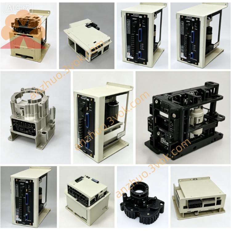
DF9200662-D0 (JANCD-MIO03) is a universal I/O expansion interface module specially designed by Yaskawa Electric Corporation for DX200/DX100/NX100 robot controllers. As a signal interaction bridge between the controller CPU and external devices, sensors, and actuators, it provides high-reliability and high-speed response digital input and output channels, supporting the signal connection and control of various switches, buttons, solenoid valves, safety equipment, etc. in industrial automation production lines. Version D0 is the latest hardware iteration of this series, optimizing signal stability, anti-interference ability, and compatibility. It is suitable for various scenarios such as welding, handling, assembly, and spraying.
II. Physical Specifications
Board Form: Standard 6U VME Industrial-grade PCB Card
Dimensions: Approximately 233mm (length) × 160mm (height) × 20mm (thickness)
Weight: Approximately 0.7kg
Interface Configuration:
VME System Bus Connector (for communication with CPU module)
CN1: 32 Digital Input Interface (24VDC, Source/Drain Type Universal)
CN2: 32 Digital Output Interface (24VDC, Transistor Output)
CN3: External 24VDC Power Input Interface (Dual Independent Power Supply)
CN4: Safety I/O Expansion Interface (8 Safety-level Auxiliary Channels)
Status LED Indicators (PWR, IN, OUT, ALM, COM, SAFE)
Structural Process:
8-layer PCB Design, strict impedance control, gold plating process to enhance signal integrity
Full-board Three-Protect Coating (dust-proof, moisture-proof, corrosion-proof), suitable for industrial harsh environments
Wide Temperature Components, Operating Temperature Range **-10°C to +60°C**
Gold-plated Connectors, Insertion and Removal Life ≥ 1000 Times
Metal Shield Cover, Enhancing EMC Anti-interference Ability
III. System Compatibility
Applicable Controllers
Motoman DX200 (Mainstream Adaptation, Firmware Ver. 6.0 and above) Motoman DX100
Motoman NX100
Version Association
Previous model: DF9200662-C0 (JANCD-MIO02)
Similar model: DF9200662-D0N (Security Enhanced Version)
Associated modules: JANCD-MCP01 (CPU board), JANCD-MIF01 (Servo Interface Board)
IV. Core Functional Characteristics
1. I/O Channel Specifications
Digital Input (DI): 32 channels, 24VDC ±10%, input current approximately 7mA/channel
Input Logic: Source-type / Drain-type universal, no hardware switching required
Response Time: <0.5ms, supports high-speed signal acquisition
Filter Function: 0 - 127ms software adjustable, suppresses signal jitter
Digital Output (DO): 32 channels, 24VDC ±10%, maximum load 0.5A/channel
Output Type: NPN Transistor, Drain-type output
Short-Circuit Protection: Independent overcurrent protection per channel, fault automatically locked
Response Time: <0.5ms, supports high-speed pulse output
Safety Auxiliary I/O: 8 channels (4 input / 4 output), compatible with safety-level signals, supports safety loop expansion
2. Communication and Control
VME bus for high-speed communication with CPU, data transmission rate 16Mbps
Supports interrupt-triggered input, up to 8 interrupts, response time < 0.1ms
Supports position comparison output, linked with robot axis control to achieve precise timing control
I/O Status Real-time Mapping to Controller Memory, supports direct program reading and writing
Supports remote I/O diagnosis, monitored channel status through teaching device or upper computer
3. Protection and Diagnostic Functions
Dual independent power supply, main power supply and I/O power supply isolated to prevent interference crosstalk
Overvoltage, undervoltage, overcurrent, reverse polarity protection, hardware-level safety protection
Channel Status LED Real-time Indication, quick fault channel location
Fault Code Precise Diagnosis, supports open circuit, short circuit, overload alarms
Watchdog Circuit, automatically cuts off output in abnormal state, ensuring equipment safety
5. Anti-interference and Reliability
Electrical isolation of signals and power supply 1500VAC, effectively isolates external interference
ESD Protection: ±15kV (air discharge), ±8kV (contact discharge)
Complies with industrial EMC standards, suitable for strong electromagnetic interference environments
MTBF (Mean Time Between Failures): >85,000 hours (40°C environment)
Working Humidity: 5% - 85% RH (no condensation), no condensation design
V. Electrical Parameters
Power Supply Parameters
System Power Supply: 5VDC ±5%, maximum 1.8A (VME bus power supply)
I/O External Power Supply: 24VDC ±10%, maximum 4.0A (Dual independent input)
Isolation Voltage: 1500VAC (signal / power / system)
Power Consumption: Approximately 12W (full load)
Signal Parameters
Digital Input High Level: 15V - 26.4V
Digital Input Low Level: 0V - 5V
Digital Output Voltage Drop: <1.0V (full load 0.5A)
Input Frequency: Maximum 100Hz (normal)/1kHz (high-speed interrupt channel)
Output Frequency: Maximum 200Hz (pulse output) Performance indicators
I/O response time: <0.5ms (input/output)
Interrupt response: <0.1ms
Channel expansion: A single controller can support up to 4 MIO modules, expanding to 128 points of DI/128 points of DO
Adapter load: Electromagnetic valves, relays, indicator lights, sensors, etc.
Six. Core upgrade of D0 version (compared to C0)
Hardware optimization
Power filter circuit strengthened, ripple suppression increased by 30%
Output driving capacity enhanced, maximum load 0.5A/channel (C0 is 0.3A)
ESD protection level improved, stronger anti-interference ability
Component lifespan optimized, working temperature extended to -10°C to +60°C
Function enhancement
Added 8 points of safety auxiliary I/O, supporting basic safety signal access
Software adjustable range of input filter parameters (0 to 127ms)
Support for remote diagnostic function of the latest DX200 firmware
Fault diagnosis accuracy improved, supports independent alarm for single channel
Compatibility expansion
Perfectly compatible with Σ-7/Σ-X series servo matching systems
Support for I/O sharing of dual robot systems
Support for third-party safety module expansion
Seven. LED status indication
PWR (green): System 5V power supply normal (always on)
IN (yellow): Digital input channel active (corresponding channel lights up)
OUT (yellow): Digital output channel active (corresponding channel lights up)
ALM (red): Fault alarm (always on = power/hardware failure, flashing = channel failure)
COM (green): VME bus communication normal (flashing)
SAFE (green): Safety auxiliary I/O normal (always on)
Eight. Installation and maintenance
Installation specification
Install in the VME standard slot of the controller (recommended 2 to 4 slots)
Grounding impedance: <1Ω, reliable double-ended grounding of the controller cabinet
Wiring requirements: I/O cables, optical fibers, power lines are separated for wiring, spacing ≥ 30mm
Connector tightening torque: 0.22 to 0.25N·m
Installation direction: Vertical installation, ensure heat dissipation space
Maintenance matters
Regularly check the tightening status of connectors to prevent loosening
Clean the board and interface every 12 months to avoid dust accumulation
Firmware upgrade only uses the officially verified version of Yaskawa
Fault replacement: Directly plug and unplug replacement, no need to reconfigure I/O addresses
Nine. Fault diagnosis and troubleshooting
ALM always on: Check 5V/24V power supply, VME bus connection, board hardware failure
No input signal: Check CN1 wiring, external power supply, input sensor, filter parameters
No output response: Check CN2 wiring, external load, output power, overcurrent protection
Communication abnormality (COM does not flash): VME bus, CPU module, firmware compatibility
Safety alarm (SAFE extinguished): Safety I/O wiring, safety circuit, external safety equipment
Ten. Safety and certification
Complies with standards: UL 508, CE (LVD/EMC), RoHS, IEC 61010
Safety auxiliary channels: ISO 13849-1 PLC, IEC 61508 SIL 1
Safety features:
Independent power isolation to prevent fault spread
Hardware protection for output short circuit
Automatic cut-off of output in abnormal conditions
Independent monitoring of safety I/O channels
Get a Quote