DF9200658-C0 (JANCD-MIF01B) Product Technical Manual
Description
DF9200658-C0 (JANCD-MIF01B) Product Technical Manual
Manufacturer: Yaskawa Electric Corporation
Product Model: DF9200658-C0
Board Code: JANCD-MIF01B
Product Type: Robot Controller Interface / Servo Communication Module
Applicable Systems: Yaskawa Motoman DX100, DX200, NX100 Robot Controllers
I. Product Overview
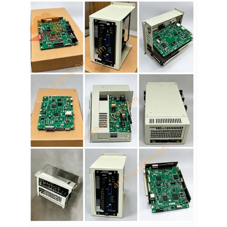
DF9200658-C0 (JANCD-MIF01B) is the core interface and servo communication module developed by Yaskawa Electric for the DX200/DX100/NX100 series robot controllers. As a signal bridge between the CPU and the servo system, external devices, it is responsible for high-speed data transmission, electrical isolation, and safety circuit management. The C0 version is a hardware upgrade of the B0 version, optimizing bus compatibility, safety functions, and anti-interference capabilities, and is suitable for industrial automation scenarios such as high-precision welding, handling, and assembly.
II. Physical Specifications
Board Form: Standard 6U VME industrial-grade PCB card
Dimensions: Approximately 233mm (length) × 160mm (height) × 20mm (thickness)
Weight: Approximately 0.6kg
Interface Configuration:
VME system bus connector (for communication with the CPU module)
CN1: SSCNET III servo optical fiber interface (8-axis control)
CN2: Encoder feedback signal interface (differential RS-422)
CN3: Teaching device dedicated communication interface
CN4: Safety I/O interface (emergency stop, STO, safety door)
CN5: External I/O expansion interface (24VDC)
CN6: System power input interface
Status LED indicators (PWR/RUN/ALM/COM/SV/SAFE)
Structural Process:
8-layer PCB, gold plating process, signal integrity enhancement
Full board three-coat coating (dust-proof, moisture-proof, corrosion-proof)
Wide-temperature components, operating temperature 0°C to +55°C
Gold-plated interfaces, plug-in and unplugging life ≥ 1000 times
III. System Compatibility
Applicable Controllers
Motoman DX200 (mainstream adaptation) Motoman DX100
Motoman NX100
Adaptive servo system
Yaskawa Σ-7 series servo drives (native support)
Yaskawa Σ-5 series servo drives
Yaskawa Σ-X series servo drives (requires firmware matching)
Version correlation
Previous model: DF9200658-B0 (JANCD-MIF01)
Subsequent model: DF9200658-C0N (Enhanced Safety Version)
Associated modules: JANCD-MCP01 (CPU board), JANCD-MSV01 (axis control board)
IV. Core functional features
1. Servo bus control
SSCNET III optical fiber bus, communication rate 1Gbps, latency < 0.2ms
Supports 8-axis synchronous control, maximum expansion to 21 axes per controller
Differential reception of encoder signals (A/B/Z phases, 4Mbps), strong anti-interference
Supports dual robot collaboration, external axis linkage, and swivel machine synchronization
Real-time diagnosis of bus disconnection and servo faults, automatic output cut-off
2. Safety function upgrade (Core advantages of C0 version)
Independent safety I/O channels, electrical isolation 1500VAC
Supports safe torque shutdown (STO), compliant with ISO 13849-1 PLd, SIL 2
Dual redundant emergency stop circuits, response time < 1ms
Access to safety door, safety scanner, safety carpet signals
Hardware latch of safety status, manual reset required after failure
3. Communication and I/O capabilities
VME bus with high-speed interaction (16Mbps)
Teaching device interface: differential transmission, maximum distance 100m
Built-in 48 points of general I/O (24 inputs / 24 outputs, 24VDC)
I/O optical isolation, response time < 0.5ms, supports source / drain type general
Supports interrupt triggering, position comparison, high-speed pulse output
5. Electrical parameters
Power requirements
Main power supply: 5VDC ±5%, maximum 2.2A
Servo interface: 24VDC ±10%, maximum 1.2A
Safety circuit: 24VDC ±10%, maximum 0.6A
Isolation voltage: 1500VAC (signal / power)
Signal specifications
SSCNET III: optical fiber, 1Gbps, single mode / multi mode compatible
Encoder: 5V differential (RS-422), maximum 4Mbps
Safety I/O: 24VDC, PLd/SIL 2 safety level
I/O: 24VDC, source / drain type general, response < 0.5ms Performance indicators
Control cycle: adjustable from 1ms to 8ms
Position accuracy: ±1 encoder pulse
Safety response: <1ms
MTBF: >90,000 hours (40°C industrial environment)
Six, Core Upgrade of Version C0 (compared with B0)
Hardware reliability
Power supply filtering enhanced by 40%, ripple suppression <0.8%
ESD protection: ±15kV (air)/±8kV (contact)
Capacitor life extended to 12 years (40°C)
Interface gold plating thickness doubled, stronger oxidation resistance
Function optimization
Comprehensive upgrade of safety functions, in line with the latest ISO standards
Support for Σ-7/Σ-X servo native adaptation
Enhanced servo bus fault-tolerant mechanism, rapid recovery in case of disconnection
Firmware encryption protection to prevent illegal tampering
Compatibility expansion
Perfectly compatible with the latest firmware of DX200 (Ver.7.0+)
Compatible with the entire series of controllers DX100/NX100
Support for remote safety diagnosis and status monitoring
Seven, LED status indication
PWR (green): 5V power supply normal (constant on)
RUN (green): system running (1 time/second flashing)
ALM (red): fault (constant on = hardware, flashing = software)
COM (yellow): VME communication active (flashing)
SV (yellow): servo bus normal (flashing)
SAFE (green): safety circuit normal (constant on)
Eight, Installation and Maintenance
Installation specification
Installed in slot 1 of the controller VME (next to the standard CPU)
Grounding impedance: <1Ω (dual-ended grounding of the cabinet)
Separate wiring of optical fiber, signal line, power line
Connector tightening torque: 0.22~0.25N·m
Maintenance matters
Regular cleaning of optical fiber to avoid dust contamination
Firmware upgrade: official verified version to prevent incompatibility
Annual safety circuit inspection to ensure normal function
Storage environment: dry, dust-proof, corrosion-resistant
Nine, Fault Diagnosis
ALM constantly on: check 5V/24V power supply, VME bus, hardware short circuit
Servo no communication: optical fiber connection, servo power, SSCNET protocol
Safety anomaly: emergency stop, safety door, STO wiring/configuration
Teaching device no response: CN3 interface, cable, differential signal
I/O failure: wiring, power supply, module configuration/address
Ten, Safety and Certification
Complies with standards: UL 508, CE (LVD/EMC), RoHS, IEC 61010
Safety certification: ISO 13849-1 PLd, IEC 61508 SIL 2
Safety features:
STO safety torque shutdown
Emergency stop hard wire direct connection, response < 1ms
Fault safety design, abnormal automatic disconnection of servo
Independent safety I/O channel, no cross-interference
Document description: This manual is based on the official parts database of ABB, the technical manual of DX200 controller, and the hardware specification of DF9200658-C0 (JANCD-MIF01B), covering core parameters, functions, compatibility, installation maintenance and fault diagnosis, applicable for product selection, debugging, maintenance and spare parts replacement.
Get a Quote