Technical Specification Sheet of DF92006500-C0 (Chinese Version)
Description
Technical Specification Sheet of DF92006500-C0 (Chinese Version)
Manufacturer: Yaskawa Electric Corporation
Product Model: DF92006500-C0
Product Type: Multi-axis Servo Control / Axis Interface Module
Applicable System: Yaskawa Motoman NX100, DX200 Robot Controller
I. Product Overview
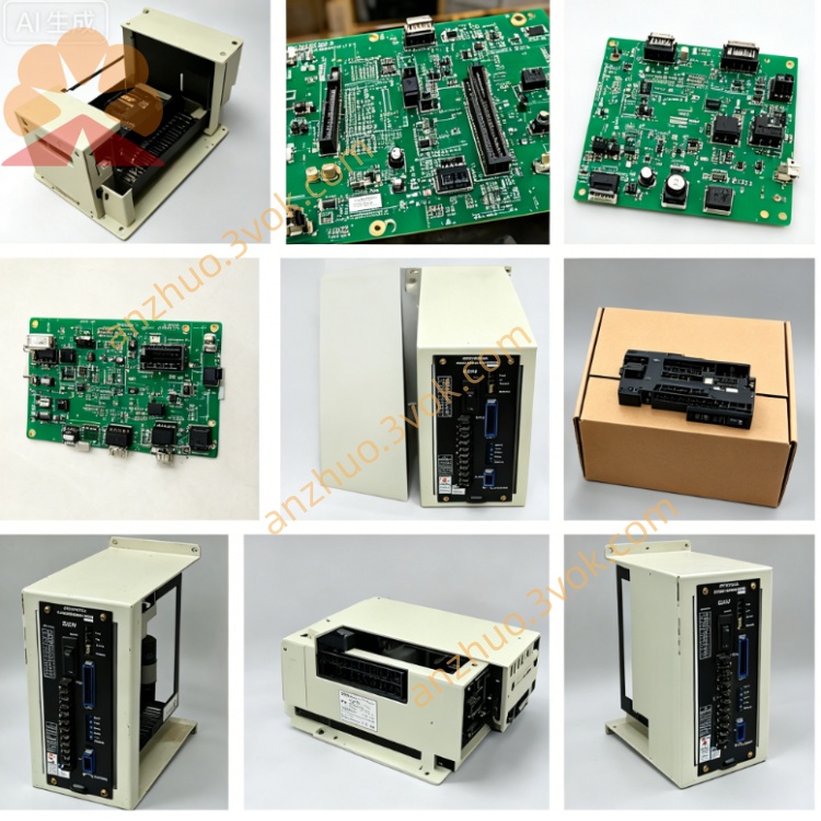
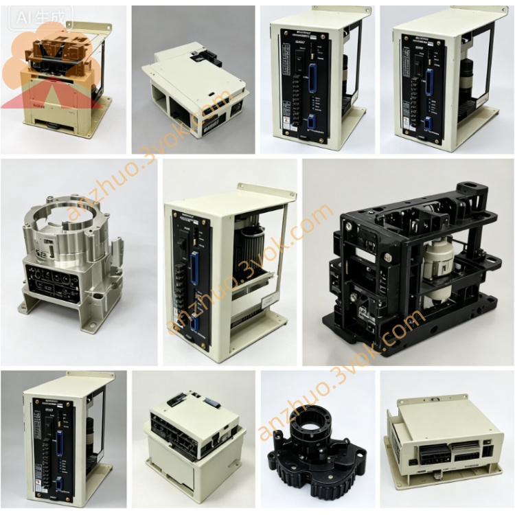
DF92006500-C0 is a high-performance multi-axis servo control circuit board developed by Yaskawa specifically for the new generation of robot controllers. As the core axis control unit of the NX100/DX200 control system, it is responsible for the command output of multi-axis motion of the robot, the collection of position feedback, real-time closed-loop control, and motion synchronization coordination, ensuring the robot's high-speed, high-precision, and stable trajectory operation. The C0 version has been comprehensively optimized in terms of hardware stability, anti-interference ability, and control accuracy compared to the previous B0 version, making it suitable for complex industrial robot application scenarios.
II. Physical Specifications
Board Form: Standard 6U VME bus industrial-grade plug-in card
Dimensions: Approximately 220mm (length) × 160mm (height) × 25mm (thickness)
Weight: Approximately 0.55kg
Interface Configuration:
CN1–CN8: 8-axis servo motor drive command interface
Encoder feedback interface (differential RS-422)
VME system bus edge connector
Auxiliary I/O terminals (fault, enable, temperature monitoring)
External encoder expansion interface
Structural Process:
8-layer industrial-grade PCB, large copper foil power lines
Three-proof coating (dust-proof, moisture-proof, oil-proof)
Surface mount + through-hole hybrid process, high shock resistance and reliability
Integrated heat dissipation path, suitable for high-temperature environments in control cabinets
III. System Compatibility
Applicable Controllers
Motoman NX100 robot controller
Motoman DX200 robot controller
Compatible Robot Series
MH series: MH6, MH12, MH24, MH50, MH80, MH165
HP series: HP6, HP20, HP50
UP series: UP6, UP20, UP50
MS, SK, YR full series industrial robots
Version Correlation
Previous version: DF92006500-B0
Subsequent version: DF92006500-D0
Associated Modules: JANCD-MSV01, JANCD-MSV02 servo control boards
IV. Core Functional Features
1. Multi-axis Motion Control
Supports independent control of 8-axis servo motors, single-axis/multi-axis synchronous operation
Real-time position loop, speed loop, and current loop three-loop closed-loop control
Supports linear, circular, and helical interpolation, trajectory accuracy ±0.001mm
Dual-robot collaborative control, up to 21-axis linkage expansion
2. High-speed Signal Processing
32-bit dedicated motion processor, 16-bit high-precision AD/DA conversion
Pulse command output frequency: up to 1MHz
Encoder feedback processing rate: 4Mbps
Control cycle: standard 250μs, high-speed mode 125μs
3. Feedback Interface Support
Incremental encoder (A/B/Z three-phase)
Absolute encoder (compatible communication protocol)
Rotary transformer signal conversion adaptation
Multi-turn position data retention after power-off
4. Protection and Diagnosis
Hardware protection for overcurrent, overvoltage, and undervoltage in axis drive
Real-time monitoring of position deviation and fault latching
Collection of motor temperature and encoder abnormal status
Direct connection of emergency stop (ESTOP) hardwired loop
Real-time indication of fault codes, supporting controller diagnosis reading
5. Communication and Data Interaction
High-speed data interaction with CPU module via VME bus
Real-time status sharing through dual-port RAM
Supports SSCNET and SERCOS servo bus protocols
Compatible with the new communication bus of the DX200 controller
V. Electrical Parameters
Power Requirements
Logic power: 5VDC ±5%, maximum 3.0A
Interface power: 24VDC ±10%, maximum 1.5A Isolation withstand voltage: 1500VAC (input/output signal isolation)
Signal specifications
Encoder input: 5V differential (RS-422)
Servo command output: ±10V analog / 24V pulse
I/O signal: 24VDC, 100mA (source type / sink type universal)
Position resolution: 0.001mm (linear) / 0.0001° (rotary)
Performance indicators
Position capture accuracy: ±1 encoder pulse
Command response time: <0.5ms
Ripple noise: <0.5% Vp-p
Control bandwidth: standard 250Hz, high speed 500Hz
VI. Environmental parameters
Operating temperature: 0°C to +45°C
Storage temperature: -20°C to +70°C
Relative humidity: 10% to 90% RH (no condensation)
Vibration: 10 to 60Hz, 0.5G (IEC 60068-2-6)
Shock: 10G, 11ms half-sine wave
Pollution degree: 2 (industrial environment)
Altitude: ≤1000m
VII. C0 version upgrade highlights
Control performance: 5V power supply ripple suppression improved by 30%, position loop response speed increased by 20%
Hardware reliability:
Electrolytic capacitors upgraded to 10-year lifespan (40°C)
Interface ESD protection level increased to ±15kV
Enhanced EMC interference resistance, suitable for strong electromagnetic environments
Function expansion:
New encoder signal verification mechanism added
Support for DX200 controller VxWorks system firmware
Fault diagnosis code expanded to 32 bits for more precise location
VIII. Installation and maintenance
Installation guidelines
Vertically installed in the dedicated slot of the NX100/DX200 controller
Grounding impedance: <1Ω (dual-end cabinet grounding)
Separate wiring for power lines and signal lines, with shield layer grounded at one end
Terminal tightening torque:
Power terminal: 1.2–1.5N・m
Signal connector: 0.22–0.25N・m
Reliability indicators
MTBF (Mean Time Between Failures): >90,000 hours (40°C)
Design life: 15 years (standard industrial environment)
ESD protection level: Class 1 (anti-static wrist strap required during operation)
Warranty: 12 months for new products, 6 months for repaired products
IX. Status indication (LED)
PWR (green): 5V logic power supply normal
RUN (green): Module operating normally
ALM (red): Hardware fault (overcurrent / overvoltage / overheating)
ENB (green): Servo enable status
AX1–AX8 (yellow): Indication of each axis' operating status
X. Fault diagnosis
No output: Check 5V/24V power supply, bus connection, enable signal
ALM red light constantly on: Disconnect load → Power on single axis → Locate faulty axis
Excessive position deviation: Verify encoder wiring, zero position calibration, mechanical clearance
Communication abnormality: Check VME slot, bus terminal resistance, controller firmware
XI. Safety and certification
Compliance standards: UL 508, CE (LVD), IEC 61010, RoHS
Safety features:
Servo torque safety cut-off (STO) compatible
Overcurrent hardware self-locking, faults cannot be automatically reset
Support for safety door and emergency stop circuit series connection
Get a Quote