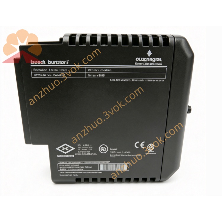
12P2506X062
Description
1. Product Overview
2. Main Features
6 fully isolated analog output channels
Software-configurable output: 4-20mA (current) or 0-10V (voltage)
16-bit high-resolution DAC for precise control
1500 VDC isolation between channels and internal logic
1:1 redundant configuration with automatic switching (≤100ms)
Hot swap capable for online replacement without system shutdown
Comprehensive diagnostics: open circuit, short circuit, and over-range detection
Wide operating temperature: -40°C to +70°C
35 mm DIN rail mountable; IP20 protection
CE, UL certified; compliant with industrial EMC standards
3. Technical Specifications
3.1 General Parameters
Model: 12P2506X062 (KJ3241X1-BA1, CE4006P2)
Manufacturer: Emerson (DeltaV)
Module Type: 6-Channel Analog Output Module
Local Bus Power: 12 VDC, 300 mA
Power Consumption: ≤8 W
Redundancy: 1:1, automatic switchover (≤100ms)
Hot Swap: Supported
3.2 Analog Output Specifications
Channel Quantity: 6 isolated channels
Output Types: 4-20mA (current), 0-10V (voltage)
Resolution: 16-bit
Basic Accuracy: ±0.05% Full Scale
Temperature Drift: ≤50 ppm/°C
Output Impedance: ≤500Ω (current), ≥10kΩ (voltage)
Overload Protection: Current: ≤28mA; Voltage: ≤12VDC
Isolation Voltage: 1500 VDC (channel-to-logic)
3.3 Environmental Ratings
Operating Temperature: -40°C to +70°C
Storage Temperature: -40°C to +85°C
Relative Humidity: 5%–95% RH, non-condensing
Vibration: 1 mm peak-peak (2–13.2 Hz); 0.7 g (13.2–150 Hz)
Shock: 10 g half-sine wave, 11 ms duration
Contaminant Rating: ISA-S71.04 Class G3
Protection Class: IP20
3.4 Mechanical & Compliance
Mounting: 35 mm standard DIN rail
Housing Material: Flame-retardant engineering plastic
Certifications: CE, UL, RoHS compliant
4. Safety Precautions
Installation, wiring, and maintenance must be performed by qualified technicians familiar with DeltaV systems and analog signal wiring.
Disconnect all power supplies (local bus and field devices) before installation, wiring, or module replacement to prevent electric shock or equipment damage.
Do not install in explosive, flammable, or highly corrosive environments unless certified for hazardous locations (Class I Div.2, Groups A,B,C,D; T4).
Use shielded twisted-pair (STP) cables for analog output wiring; separate from high-voltage AC cables to avoid EMI.
Cable shields must be grounded at one end only to eliminate circulating current interference.
Do not exceed the module’s output ratings (4-20mA / 0-10V).
Unauthorized disassembly or modification of the module is prohibited; voids warranty.
5. Installation & Terminal Definition
5.1 DIN Rail Installation
Secure a 35 mm DIN rail vertically in the control cabinet.
Hook the module’s upper latch onto the rail edge.
Press downward until the bottom lock clicks into place.
Verify firm mounting by gently shaking the module.
5.2 Terminal Pin Assignment
Channel 1:
1: CH1+ (Output Positive)
2: CH1- (Output Negative)
Channel 2:
3: CH2+
4: CH2-
Channel 3:
5: CH3+
6: CH3-
Channel 4:
7: CH4+
8: CH4-
Channel 5:
9: CH5+
10: CH5-
Channel 6:
11: CH6+
12: CH6-
Power & Ground:
13: 12 VDC (Local Bus Power)
14: GND (Local Bus Ground)
15: FG (Frame Ground)
5.3 Wiring Instructions
Strip 6 mm of insulation from STP cable ends; insert into terminals and tighten screws to 0.5–0.6 N·m.
Current Output (4-20mA): Connect actuator/valve positive to CHx+ and negative to CHx-.
Voltage Output (0-10V): Connect actuator/indicator positive to CHx+ and negative to CHx-.
Connect cable shield to the “FG” terminal; ground at the module end only.
Avoid parallel routing with 480 VAC or motor cables; maintain ≥30 cm separation.
6. Parameter Configuration
Open DeltaV Explorer; navigate to the I/O System and add the 12P2506X062 module.
Assign module address, rack, and slot number matching physical installation.
Configure each output channel:
Select output type (4-20mA or 0-10V)
Set engineering range and unit
Configure fail-safe state (hold, 0%, 100%)
Enable diagnostics (open circuit, short circuit alarms)
Configure redundancy (if applicable):
Assign primary and secondary module addresses
Enable automatic switchover
Download configuration to the DeltaV controller and module.
Verify output operation: check channel status and real-time values in DeltaV Operate.
7. Operation Description
7.1 Power-on Self-Test
7.2 Main Functions
Converts digital DCS control signals to 4-20mA / 0-10V analog outputs.
Drives field devices: control valves, actuators, positioners, and indicators.
Supports redundant operation (1:1) for high-availability systems.
Provides hot swap capability for online module replacement.
Monitors channel health: detects open circuit, short circuit, and over-range conditions.
Supports fail-safe configuration (hold last value, 0%, or 100% on fault).
7.3 Indicator Status
PWR (Green): Steady = Local bus power normal; Off = No power
COM (Green): Flashing = Communication active; Off = No communication
ERR (Red): Flashing = Channel fault; Steady = Module hardware failure
CH1–CH6 (Yellow): On = Channel active; Flashing = Channel fault
8. Daily Maintenance
Inspect terminal connections quarterly for tightness, corrosion, or loose wires.
Clean module surface with a dry, soft cloth; avoid liquid cleaners.
Check cable integrity annually for damage, aging, or poor shielding.
Verify redundancy switchover operation semi-annually (if applicable).
Review DeltaV diagnostic logs monthly for channel faults or communication errors.
9. Troubleshooting
- PWR LED Off
Cause: No 12 VDC local bus power or reversed polarity
Solution: Check power supply wiring and voltage (12 VDC ±10%)
- COM LED Off (No Communication)
Cause: Incorrect address setting, loose backplane contact, or communication failure
Solution: Verify address, re-seat module, and check bus connection
- ERR LED Flashing (Channel Fault)
Cause: Open circuit, short circuit, or over-range output
Solution: Check field device wiring, verify load resistance, and confirm output range configuration
- Output Signal Unstable
Cause: Loose wiring, lack of shielding, or strong electromagnetic interference
Solution: Fasten terminals, use shielded cable with single-end grounding, and relocate away from interference sources
- Redundancy Switchover Failure
Cause: Incorrect redundancy configuration or faulty secondary module
Solution: Verify redundancy settings, check secondary module status, and test switchover
Get a Quote