12P2471X042
Description
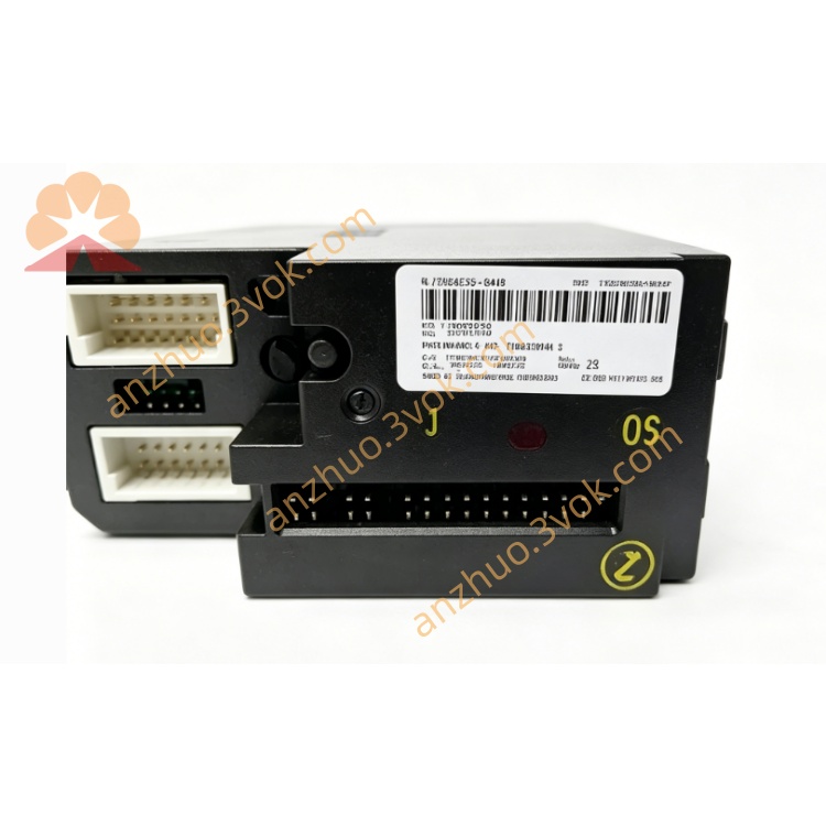
1. Product Overview
2. Main Features
2 isolated FOUNDATION Fieldbus H1 ports (31.25 kbps)
Seamless integration with Emerson DeltaV DCS (Series 2 compatible)
Supports FF H1 device configuration, control strategies, and diagnostics
12 VDC local bus power (300 mA) and 9–32 VDC fieldbus power (12 mA per port)
Extended operating temperature: -40°C to +70°C
High vibration/shock resistance (1 mm pp 2–13.2 Hz; 0.7 g 13.2–150 Hz)
ISA-S71.04 Class G3 airborne contaminant rating
IP20 protection; 35 mm DIN rail mountable
CE, UL certified; compliant with industrial EMC standards
3. Technical Specifications
3.1 General Parameters
Model: 12P2471X042 (KJ3242X1-BA1)
Manufacturer: Emerson (DeltaV)
Module Type: FOUNDATION Fieldbus H1 Communication Card
Number of Ports: 2 (isolated)
Communication Speed: 31.25 kbps (FF H1 standard)
Local Bus Power: 12 VDC, 300 mA
Fieldbus Power: 9–32 VDC, 12 mA per port
Power Consumption: ≤10 W
3.2 Environmental Ratings
Operating Temperature: -40°C to +70°C
Storage Temperature: -40°C to +85°C
Relative Humidity: 5%–95% RH, non-condensing
Vibration: 1 mm peak-peak (2–13.2 Hz); 0.7 g (13.2–150 Hz)
Shock: 10 g half-sine wave, 11 ms duration
Contaminant Rating: ISA-S71.04 Class G3
Protection Class: IP20
3.3 Mechanical & Compliance
Mounting: 35 mm standard DIN rail
Housing Material: Flame-retardant engineering plastic
Certifications: CE, UL, RoHS compliant
4. Safety Precautions
Installation, wiring, and maintenance must be performed by qualified technicians familiar with DeltaV systems and FOUNDATION Fieldbus.
Disconnect all power supplies (local bus and fieldbus) before installation, wiring, or module replacement to prevent electric shock or equipment damage.
Do not install in explosive, flammable, or highly corrosive environments unless certified for hazardous locations.
Use shielded twisted-pair (STP) cables for Fieldbus H1 wiring; separate from high-voltage AC cables to avoid EMI.
Cable shields must be grounded at one end only to eliminate circulating current interference.
Do not exceed the module’s voltage/current ratings (9–32 VDC fieldbus; 12 VDC local bus).
Unauthorized disassembly or modification of the module is prohibited; voids warranty.
5. Installation & Terminal Definition
5.1 DIN Rail Installation
Secure a 35 mm DIN rail vertically in the control cabinet.
Hook the module’s upper latch onto the rail edge.
Press downward until the bottom lock clicks into place.
Verify firm mounting by gently shaking the module.
5.2 Terminal Pin Assignment (Port 1 & Port 2)
Port 1:
1: FB1+ (Signal/Power Positive)
2: FB1- (Signal/Power Negative)
3: Shield (Cable Shield Ground)
4: NC (No Connection)
Port 2:
5: FB2+ (Signal/Power Positive)
6: FB2- (Signal/Power Negative)
7: Shield (Cable Shield Ground)
8: NC (No Connection)
Power & Ground:
9: 12 VDC (Local Bus Power)
10: GND (Local Bus Ground)
11: FG (Frame Ground)
5.3 Wiring Instructions
Strip 6 mm of insulation from STP cable ends; insert into terminals and tighten screws to 0.5–0.6 N·m.
Connect Fieldbus H1 devices in a truncated bus topology (max 32 devices per port, 1900 m total length).
Terminate each bus segment with 120 Ω resistors at both ends (integrated in most FF devices).
Connect cable shield to the “Shield” terminal; ground at the module end only.
Avoid parallel routing with 480 VAC or motor cables; maintain ≥30 cm separation.
6. Parameter Configuration
Open DeltaV Explorer; navigate to the I/O System and add the 12P2471X042 module.
Assign module address, rack, and slot number matching physical installation.
Configure each H1 port:
Enable/disable port
Set bus address (1–255)
Configure baud rate (fixed at 31.25 kbps)
Assign Fieldbus device tags and process variables
Enable device diagnostics (loop current, voltage, communication errors)
Download configuration to the DeltaV controller and module.
Verify bus communication: check device status and real-time data in DeltaV Operate.
7. Operation Description
7.1 Power-on Self-Test
7.2 Main Functions
Acts as DeltaV DCS interface for FOUNDATION Fieldbus H1 devices.
Transmits process data (temperature, pressure, flow) between field devices and DCS.
Downloads configuration parameters to FF H1 devices (e.g., sensor ranges, control modes).
Monitors bus health: detects communication errors, device faults, and voltage anomalies.
Supports redundant operation (optional) for high-availability systems.
7.3 Indicator Status
PWR (Green): Steady = Local bus power normal; Off = No power
COM (Green): Flashing = Bus communication active; Off = No device communication
ERR (Red): Flashing = Port/device fault; Steady = Module hardware failure
LINK (Yellow): On = Fieldbus link active; Off = Link down
8. Daily Maintenance
Inspect terminal connections quarterly for tightness, corrosion, or loose wires.
Clean module surface with a dry, soft cloth; avoid liquid cleaners.
Check cable integrity annually for damage, aging, or poor shielding.
Verify bus termination resistors (120 Ω) are intact and properly installed.
Review DeltaV diagnostic logs monthly for communication errors or device faults.
9. Troubleshooting
- PWR LED Off
Cause: No 12 VDC local bus power or reversed polarity
Solution: Check power supply wiring and voltage (12 VDC ±10%)
- COM LED Off (No Device Communication)
Cause: Incorrect bus address, missing termination, or faulty wiring
Solution: Verify address setting, check 120 Ω terminators, and test cable continuity
- ERR LED Flashing
Cause: Fieldbus short circuit, device overload, or voltage out of range
Solution: Inspect bus for shorts, reduce device count, and check fieldbus power (9–32 VDC)
- Intermittent Communication
Cause: EMI interference, loose connections, or incorrect shielding
Solution: Separate signal cables from high-voltage lines, tighten terminals, and ensure single-end shielding
Get a Quote