12P2186X012
Description
1.
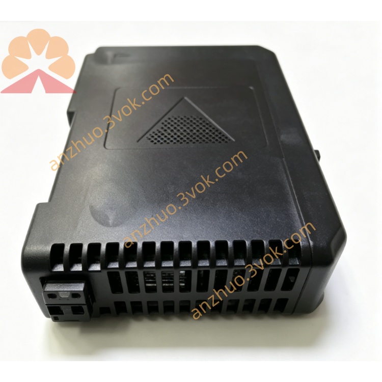
1. Product Overview
2. Main Features
8 fully isolated analog input channels
Supports both current (4-20mA) and voltage (0-10V) signal types
16-bit high-resolution ADC for precise measurement
1500 VDC isolation between field side and internal logic circuit
Software-configurable signal type, range, and digital filtering
Built-in fault diagnosis: open circuit, short circuit, and over-range detection
Industrial wide temperature range: 0°C to +60°C
Standard 35 mm DIN rail mounting for easy installation
Compliant with industrial EMC standards for strong anti-interference performance
Low power consumption and high reliability for continuous operation
3. Technical Specifications
3.1 General Parameters
Model: 12P2186X012
Rated Power Supply: 24 VDC ±10%
Operating Current: ≤300 mA
Isolation Voltage: 1500 VDC (field to logic)
Operating Temperature: 0°C ~ +60°C
Storage Temperature: -40°C ~ +85°C
Relative Humidity: 5% ~ 95% RH, non-condensing
Mounting: 35 mm standard DIN rail
Housing Material: Flame-retardant engineering plastic
3.2 Analog Input Specifications
Channel Quantity: 8 isolated channels
Signal Types: 4-20mA (current), 0-10V (voltage)
Resolution: 16-bit
Basic Accuracy: ±0.05% Full Scale
Temperature Drift: ≤50 ppm/°C
Input Impedance: ≥1MΩ (voltage), ≤250Ω (current)
Overvoltage Protection: Up to 30VDC
Overcurrent Protection: Up to 50mA
3.3 Communication & Diagnosis
Communication Interface: DCS/PLC backplane bus
Diagnostic Functions: Open circuit, short circuit, over-range, under-range detection
Configuration: Remote parameter setting via system software
4. Safety Precautions
Installation, wiring, and maintenance must be performed by qualified professional technicians.
Disconnect all power supplies before wiring, disassembly, or module replacement to avoid electric shock and equipment damage.
Do not install in flammable, explosive, dusty, or highly corrosive environments without proper certification.
Use shielded twisted-pair cables for analog signal wiring; separate signal cables from high-voltage power cables.
The cable shield must be grounded at a single end only to prevent circulating current interference.
Strictly follow standard wiring practices; incorrect connections may cause measurement errors or module damage.
Do not input signals beyond the module’s rated range.
Unauthorized disassembly or modification of the internal circuit is prohibited.
5. Installation and Terminal Definition
5.1 DIN Rail Installation
Secure a 35 mm standard DIN rail firmly on the installation panel.
Hook the module’s upper buckle onto the DIN rail edge.
Press downward until the bottom lock snaps into place.
Gently shake the module to confirm it is securely installed.
5.2 Terminal Pin Assignment
5.3 Wiring Instructions
Strip approximately 6 mm of insulation from wire ends, insert into corresponding terminals, and tighten screws moderately.
Current Signal (4-20mA): Connect positive wire to CHx+ and negative wire to CHx-.
Voltage Signal (0-10V): Connect positive wire to CHx+ and negative wire to CHx-.
Use shielded twisted-pair cable for long-distance transmission; ground the shield at one end only.
Avoid routing signal cables parallel to high-power AC lines to reduce electromagnetic interference.
6. Parameter Configuration
Add the 12P2186X012 module in your DCS or PLC configuration software.
Set the module address, rack, and slot number according to the actual hardware position.
Configure parameters for each channel:
Select signal type (4-20mA or 0-10V)
Set engineering range and unit
Adjust digital filter time constant
Enable open circuit, short circuit, and over-range alarms
Download the configuration to the controller and module.
Verify real-time signal values to ensure normal acquisition accuracy.
7. Operation Description
7.1 Power-on Self-test
7.2 Main Functions
Collect analog signals (4-20mA/0-10V) from field sensors and transmitters.
Convert analog signals to digital values via a 16-bit ADC.
Perform digital filtering, linearization, and scaling internally.
Upload processed data to the DCS/PLC system in real time.
Detect and report channel faults (open circuit, short circuit, over-range).
Accept remote configuration to adapt to different signal types and ranges.
7.3 Indicator Status Description
Power LED Steady Green: Power supply normal
Power LED Off: No power or power fault
Status LED Green Flashing: Normal operation, no faults
Status LED Red Flashing: Channel fault (open/short/over-range)
Status LED Steady Red: Hardware failure, replace module
Channel LED On: Channel working normally
Channel LED Flashing: Corresponding channel abnormal
8. Daily Maintenance
Regularly check terminal tightness to prevent oxidation, corrosion, and loose connections.
Clean module surface dust with a dry soft cloth only; do not use liquid or chemical solvents.
Keep ambient temperature and humidity within specified ranges.
Periodically inspect signal cables for aging, damage, or poor contact; replace if abnormal.
Regular calibration is recommended to ensure long-term measurement accuracy.
9. Troubleshooting
- Power indicator not lit
Cause: No 24VDC input, reversed polarity, or broken power wire
Solution: Check power supply and correct wiring polarity
- System cannot recognize the module
Cause: Incorrect address setting, loose backplane contact, or communication failure
Solution: Confirm address, re-seat module, and check bus connection
- Unstable or fluctuating signal values
Cause: Loose wiring, lack of shielding, or strong electromagnetic interference
Solution: Fasten terminals, use shielded cable with single-end grounding, and relocate away from interference sources
- Large measurement deviation
Cause: Wrong signal type or range configuration
Solution: Re-select correct signal type and matching range
- Channel open circuit alarm
Cause: Field sensor/transmitter failure or signal wire breakage
Solution: Check field device and wiring continuity
10. Warranty Statement
2. Main Features
8 fully isolated analog input channels
Supports both current (4-20mA) and voltage (0-10V) signal types
16-bit high-resolution ADC for precise measurement
1500 VDC isolation between field side and internal logic circuit
Software-configurable signal type, range, and digital filtering
Built-in fault diagnosis: open circuit, short circuit, and over-range detection
Industrial wide temperature range: 0°C to +60°C
Standard 35 mm DIN rail mounting for easy installation
Compliant with industrial EMC standards for strong anti-interference performance
Low power consumption and high reliability for continuous operation
3. Technical Specifications
3.1 General Parameters
Model: 12P2186X012
Rated Power Supply: 24 VDC ±10%
Operating Current: ≤300 mA
Isolation Voltage: 1500 VDC (field to logic)
Operating Temperature: 0°C ~ +60°C
Storage Temperature: -40°C ~ +85°C
Relative Humidity: 5% ~ 95% RH, non-condensing
Mounting: 35 mm standard DIN rail
Housing Material: Flame-retardant engineering plastic
3.2 Analog Input Specifications
Channel Quantity: 8 isolated channels
Signal Types: 4-20mA (current), 0-10V (voltage)
Resolution: 16-bit
Basic Accuracy: ±0.05% Full Scale
Temperature Drift: ≤50 ppm/°C
Input Impedance: ≥1MΩ (voltage), ≤250Ω (current)
Overvoltage Protection: Up to 30VDC
Overcurrent Protection: Up to 50mA
3.3 Communication & Diagnosis
Communication Interface: DCS/PLC backplane bus
Diagnostic Functions: Open circuit, short circuit, over-range, under-range detection
Configuration: Remote parameter setting via system software
4. Safety Precautions
Installation, wiring, and maintenance must be performed by qualified professional technicians.
Disconnect all power supplies before wiring, disassembly, or module replacement to avoid electric shock and equipment damage.
Do not install in flammable, explosive, dusty, or highly corrosive environments without proper certification.
Use shielded twisted-pair cables for analog signal wiring; separate signal cables from high-voltage power cables.
The cable shield must be grounded at a single end only to prevent circulating current interference.
Strictly follow standard wiring practices; incorrect connections may cause measurement errors or module damage.
Do not input signals beyond the module’s rated range.
Unauthorized disassembly or modification of the internal circuit is prohibited.
5. Installation and Terminal Definition
5.1 DIN Rail Installation
Secure a 35 mm standard DIN rail firmly on the installation panel.
Hook the module’s upper buckle onto the DIN rail edge.
Press downward until the bottom lock snaps into place.
Gently shake the module to confirm it is securely installed.
5.2 Terminal Pin Assignment
5.3 Wiring Instructions
Strip approximately 6 mm of insulation from wire ends, insert into corresponding terminals, and tighten screws moderately.
Current Signal (4-20mA): Connect positive wire to CHx+ and negative wire to CHx-.
Voltage Signal (0-10V): Connect positive wire to CHx+ and negative wire to CHx-.
Use shielded twisted-pair cable for long-distance transmission; ground the shield at one end only.
Avoid routing signal cables parallel to high-power AC lines to reduce electromagnetic interference.
6. Parameter Configuration
Add the 12P2186X012 module in your DCS or PLC configuration software.
Set the module address, rack, and slot number according to the actual hardware position.
Configure parameters for each channel:
Select signal type (4-20mA or 0-10V)
Set engineering range and unit
Adjust digital filter time constant
Enable open circuit, short circuit, and over-range alarms
Download the configuration to the controller and module.
Verify real-time signal values to ensure normal acquisition accuracy.
7. Operation Description
7.1 Power-on Self-test
7.2 Main Functions
Collect analog signals (4-20mA/0-10V) from field sensors and transmitters.
Convert analog signals to digital values via a 16-bit ADC.
Perform digital filtering, linearization, and scaling internally.
Upload processed data to the DCS/PLC system in real time.
Detect and report channel faults (open circuit, short circuit, over-range).
Accept remote configuration to adapt to different signal types and ranges.
7.3 Indicator Status Description
Power LED Steady Green: Power supply normal
Power LED Off: No power or power fault
Status LED Green Flashing: Normal operation, no faults
Status LED Red Flashing: Channel fault (open/short/over-range)
Status LED Steady Red: Hardware failure, replace module
Channel LED On: Channel working normally
Channel LED Flashing: Corresponding channel abnormal
8. Daily Maintenance
Regularly check terminal tightness to prevent oxidation, corrosion, and loose connections.
Clean module surface dust with a dry soft cloth only; do not use liquid or chemical solvents.
Keep ambient temperature and humidity within specified ranges.
Periodically inspect signal cables for aging, damage, or poor contact; replace if abnormal.
Regular calibration is recommended to ensure long-term measurement accuracy.
9. Troubleshooting
- Power indicator not lit
Cause: No 24VDC input, reversed polarity, or broken power wire
Solution: Check power supply and correct wiring polarity
- System cannot recognize the module
Cause: Incorrect address setting, loose backplane contact, or communication failure
Solution: Confirm address, re-seat module, and check bus connection
- Unstable or fluctuating signal values
Cause: Loose wiring, lack of shielding, or strong electromagnetic interference
Solution: Fasten terminals, use shielded cable with single-end grounding, and relocate away from interference sources
- Large measurement deviation
Cause: Wrong signal type or range configuration
Solution: Re-select correct signal type and matching range
- Channel open circuit alarm
Cause: Field sensor/transmitter failure or signal wire breakage
Solution: Check field device and wiring continuity
Get a Quote