12P0678X032
Description
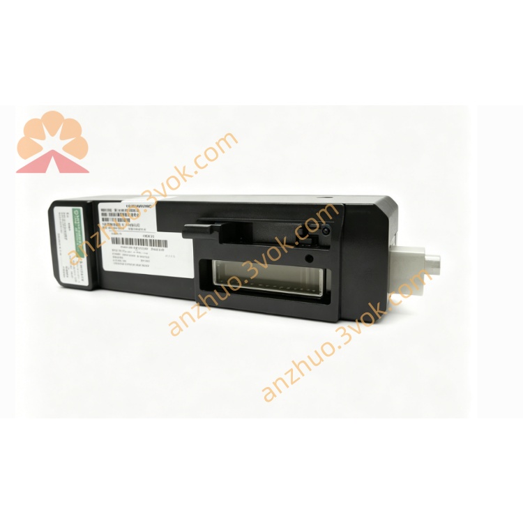
1. Product Overview
2. Main Features
Hybrid I/O integration: 4AI / 2AO / 8DI / 4DO, compatible with 4–20 mA / 0–10 V standard signals.
16‑bit ADC/DAC: High accuracy (±0.1% FS typical) and low temperature drift (±0.2% FS over range).
Software‑configurable: Signal type, engineering range, digital filtering, and operating mode.
Full protection: Electrical isolation (1500 VDC), overvoltage, overcurrent, short‑circuit, and overtemperature.
RS485 communication: Modbus RTU, default 9600 bps (configurable: 9600/19200/38400 bps).
Wide temperature: −25 °C to +60 °C; storage −40 °C to +85 °C.
Digital channels: NPN/PNP selectable; debounce time 0–500 ms adjustable.
Analog channels: Digital filtering; fail‑safe (fixed/hold) on communication loss.
Flame‑retardant housing: Compact, low power, high reliability; standard 35 mm DIN‑rail mounting.
3. Technical Specifications
3.1 General
Model: 12P0678X032
Power supply: 24 VDC ±10%
Max current: 300 mA
Isolation: 1500 VDC (field ↔ internal)
Operating temp: −25 °C to +60 °C
Storage temp: −40 °C to +85 °C
Humidity: 5–95% RH, non‑condensing
Mounting: 35 mm DIN‑rail
Housing: Industrial flame‑retardant plastic
3.2 Channel Configuration
Analog Input (AI): 4 ch, 4–20 mA / 0–10 V (software selectable)
Analog Output (AO): 2 ch, 4–20 mA / 0–10 V (software selectable)
Digital Input (DI): 8 ch, 24 VDC level compatible
Digital Output (DO): 4 ch, 0.5 A per channel (max load)
3.3 Analog Performance
Resolution: 16‑bit
Accuracy: ±0.1% FS (25 °C)
Temp drift: ±0.2% FS (−25 °C to +60 °C)
AI load: Current ≤ 250 Ω; Voltage ≥ 100 kΩ
AO load: Current ≤ 500 Ω; Voltage ≥ 1 kΩ
3.4 Communication
Interface: RS485
Protocol: Modbus RTU
Default baud: 9600 bps
Data format: 8N1 (8 data, 1 stop, no parity)
Station address: 1–247 configurable
4. Safety Precautions
Installation, wiring, and maintenance must be performed by qualified personnel.
Disconnect power before wiring, disassembly, or maintenance to avoid electric shock.
Do not install in explosive, flammable, corrosive, or conductive dust environments.
Provide adequate ventilation; do not block heat dissipation gaps.
Separate signal and power cables to reduce EMI.
Connect the protective earth terminal to a reliable ground.
Do not exceed channel rated loads to prevent permanent damage.
Do not disassemble or modify the module without authorization.
5. Installation and Terminal Definition
5.1 DIN‑Rail Installation
Secure a standard 35 mm DIN‑rail to the panel.
Align the module’s upper clip with the rail edge.
Press downward until the bottom latch clicks into place.
Shake gently to confirm firm mounting.
5.2 Terminal Pin Assignment
| Pin | Description |
|---|---|
| 1 | 24 VDC Power Positive |
| 2 | 24 VDC Power Negative |
| 3 | AI1+ |
| 4 | AI1− |
| 5 | AI2+ |
| 6 | AI2− |
| 7 | AI3+ |
| 8 | AI3− |
| 9 | AI4+ |
| 10 | AI4− |
| 11 | AO1+ |
| 12 | AO1− |
| 13 | AO2+ |
| 14 | AO2− |
| 15 | DI Common |
| 16 | DI1 |
| 17 | DI2 |
| 18 | DI3 |
| 19 | DI4 |
| 20 | DI5 |
| 21 | DI6 |
| 22 | DI7 |
| 23 | DI8 |
| 24 | DO1 |
| 25 | DO2 |
| 26 | DO3 |
| 27 | DO4 |
| 28 | DO Common |
| 29 | Protective Ground (PE) |
5.3 Wiring Instructions
Strip 6 mm of insulation from wire ends.
Loosen terminal screws with a standard screwdriver.
Insert wires per the pin assignment; tighten screws securely (do not over‑tighten).
Use cable ties to relieve strain on terminals.
Analog signals: shielded twisted pair, single‑end grounded.
Digital/power cables: Stranded copper wire of suitable gauge.
6. Parameter Configuration
6.1 Connection
6.2 Configurable Parameters
Analog Input
Signal type: 4–20 mA / 0–10 V
Custom engineering range
Digital filter: enable / disable, coefficient adjustment
Analog Output
Signal type: 4–20 mA / 0–10 V
Output calibration
Fail‑safe: fixed value / hold last value (on communication loss)
Digital Input
Logic: NPN/PNP
Debounce time: 0–500 ms
Digital Output
Logic: NPN/PNP
Fail‑safe: ON / OFF (on communication loss)
Pulse mode: width and interval settings
Communication
Baud rate: 9600 / 19200 / 38400 bps
Modbus address: 1–247
Restore factory defaults
6.3 Save & Activate
7. Operation Description
7.1 Power‑on Self‑Test
7.2 Operating Modes
AI: Acquire sensor analog signals → convert to digital → transmit to controller.
AO: Receive control commands → convert to analog → drive valves/actuators.
DI: Detect switch/sensor on‑off states → upload status changes.
DO: Control external relays, solenoids, indicators per system commands.
Communication: Exchange data/parameters with host via Modbus RTU.
7.3 LED Indicators
Power (Green, steady): Normal power
Power (Off): No power or fault
Status (Green, flashing): Normal operation / communication active
Status (Red, flashing): Overload, short circuit, or communication error
Status (Red, steady): Hardware failure → replace module
8. Maintenance
Periodically check LED status and terminal tightness; inspect for oxidation or looseness.
Clean only with a dry soft cloth; no liquid/chemical solvents.
Maintain ambient temp/humidity within specifications.
Inspect cables for aging; replace damaged wiring promptly.
Recalibrate analog channels if data is unstable or inaccurate.
9. Troubleshooting
- Power LED off
Cause: No 24 VDC, reverse polarity, or broken wire
Solution: Check power supply and wiring polarity
- Communication failure
Cause: Wrong baud rate/address, A/B lines reversed, missing termination resistor
Solution: Match parameters, correct wiring, add 120 Ω termination
- AI data unstable
Cause: Loose terminals, incorrect range, or EMI
Solution: Secure wiring, confirm signal type, use shielded cable and proper grounding
- AO inaccurate
Cause: Incorrect range or load mismatch
Solution: Reset engineering range; verify load resistance
- DI no response
Cause: Wrong logic or loose wiring
Solution: Adjust NPN/PNP setting; tighten terminals
- DO no action
Cause: Overload or incorrect logic
Solution: Reduce load to ≤0.5 A/channel; reconfigure logic
Get a Quote