1275331PSB100VMc1-6
Description
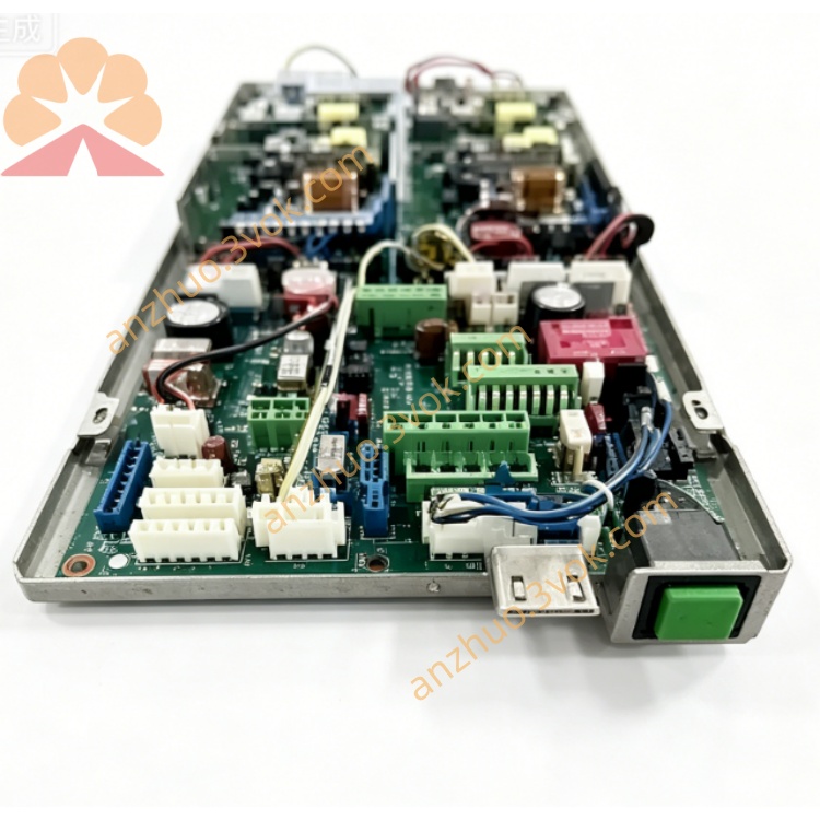
1. Product Overview
2. Main Features
Professional 6-channel DC voltage high-precision synchronous acquisition design
High-resolution sampling chip, ensuring stable and accurate signal conversion
Built-in electrical isolation, effectively isolating industrial site interference and protecting backend equipment
Integrated overvoltage, reverse connection, overcurrent and surge protection functions
Support standard industrial voltage signal input, suitable for mainstream field sensors and equipment
Compact structure, easy DIN rail mounting, convenient installation and wiring
Low power consumption, long-term stable continuous operation
Strong EMC anti-interference ability, adaptable to harsh industrial electromagnetic environment
Support software parameter configuration, channel calibration and data filtering setting
3. Technical Specifications
3.1 General Parameters
3.2 Acquisition Channel Parameters
3.3 Communication Parameters
4. Safety Precautions
Installation, wiring and maintenance must be operated by qualified professional technicians.
Cut off all power supply before wiring, installation or maintenance work to avoid electric shock and module damage.
Do not install the module in environment with flammable gas, explosive dust or strong corrosive gas.
Keep enough ventilation space around the module, do not block heat dissipation gaps.
Signal lines and power lines shall be laid separately to avoid electromagnetic interference.
The grounding terminal must be connected to reliable protective earth ground.
Do not input voltage beyond the rated range to prevent permanent burnout of the module.
Do not disassemble or modify the internal circuit structure without authorization.
5. Installation and Terminal Description
5.1 DIN Rail Installation
Fix standard 35mm DIN rail firmly on the mounting base.
Buckle the module upper card slot onto the DIN rail edge.
Press the module downward until the bottom lock snaps tightly.
Shake the module slightly to confirm firm installation without loosening.
5.2 Terminal Definition
5.3 Wiring Instructions
Strip about 6mm insulation layer at wire ends.
Loosen terminal screws with a screwdriver, insert wires into corresponding terminals.
Tighten screws moderately to ensure good contact, avoid over-tightening damage.
Voltage signal lines are recommended to use shielded twisted-pair cable.
Fix wiring with cable ties to prevent pulling and loose contact.
Do not mix high-voltage circuit and signal circuit wiring.
6. Parameter Configuration
6.1 Connection Method
6.2 Configurable Items
Modbus communication address and baud rate setting
Channel enable/disable configuration
Digital filtering coefficient adjustment
Upper and lower limit alarm threshold setting
Channel manual calibration and zero point correction
Restore factory default parameters
6.3 Save and Take Effect
7. Working Principle and Operation
7.1 Power-on Self-test
7.2 Working Description
The module performs real-time cyclic sampling of 6-channel DC voltage signals.
Internal circuit isolates, filters and converts the collected signals.
Convert analog voltage signals into standard digital Modbus data.
Upper computer or PLC reads each channel voltage data through RS485 Modbus RTU.
Support real-time monitoring, data recording and over-limit alarm function.
7.3 Indicator Status
8. Daily Maintenance
Regularly check terminal wiring tightness, prevent oxidation and loose contact.
Clean module surface dust regularly with dry soft cloth, do not use liquid solvent.
Keep working environment temperature and humidity within rated range.
Regularly check aging of signal cables and power lines, replace damaged wires in time.
If abnormal data occurs, recalibrate channel parameters and check wiring.
9. Troubleshooting
- No power indicatorCause: No 24VDC input, reverse power polarity or wire breakSolution: Check power supply and wiring, correct polarity
- Communication failureCause: Wrong baud rate/address, RS485 A/B reversed, bus terminal resistance missingSolution: Unify communication parameters, adjust A/B wiring, add matching terminal resistor
- Abnormal voltage acquisition dataCause: Signal wiring loose, input over-range or site interference too strongSolution: Fasten wiring, confirm input within 0~100VDC, use shielded cable and good grounding
- Individual channel no dataCause: Single channel input circuit fault or wiring disconnectionSolution: Check channel input wiring, recalibrate or replace module if hardware damaged
Get a Quote