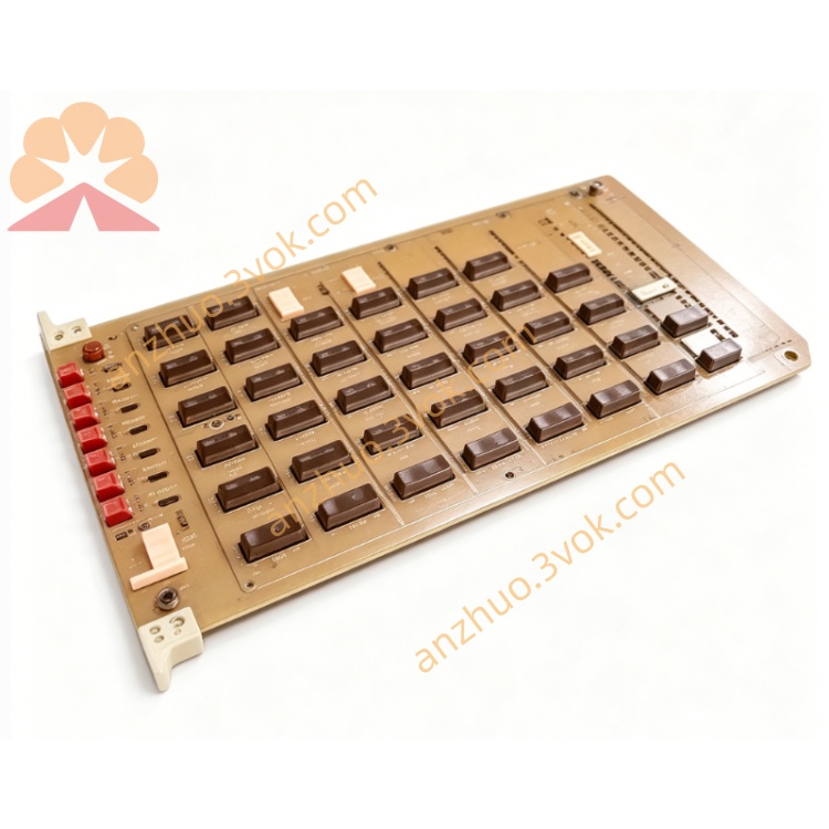
1172C25
Description
1. General Information
1.1 Product Overview
1.2 Key Features
Multi-Signal Compatibility: Supports analog (4–20 mA, 0–10 V), digital (24 V DC), and RS-485 serial inputs.
High Precision: 16-bit resolution with ±0.1% full-scale accuracy.
Signal Conditioning: Built-in filtering, amplification, and isolation for noise immunity.
Industrial Durability: Rugged construction for harsh environments.
Easy Integration: Standard DIN rail mounting and software-configurable parameters.
1.3 Specifications
Model: 1172C25
Manufacturer: Emerson
Input Types: Analog, Digital, RS-485
Resolution: 16-bit
Accuracy: ±0.1% FS
Power Supply: 24 V DC ±10%, 150 mA
Operating Temperature: -25°C to +60°CEmerson
Storage Temperature: -40°C to +85°CEmerson
Humidity: 5%–95% RH (non-condensing)Emerson
Isolation: 1500 V DC (input-to-power)
Dimensions: 120 mm × 80 mm × 25 mm
Weight: 350 g
2. Safety Precautions
Installation: Only qualified personnel should install and service this module.
Power Off: Disconnect all power before wiring to avoid electric shock.
Environment: Avoid explosive, corrosive, or conductive dust environments.
Ventilation: Maintain 25 mm clearance around the module for coolingEmerson.
Cable Routing: Separate signal and power cables to reduce interference.
Grounding: Connect the module’s ground terminal to a reliable earth ground.
3. Installation
3.1 DIN Rail Mounting
Ensure the DIN rail is clean and securely mounted.
Align the module’s top hooks with the rail.
Press the module downward until it snaps into place.
Verify the module is firmly attached and cannot be moved.
3.2 Wiring
3.2.1 Terminal Assignment
| Terminal | Description |
|---|---|
| 1 | 24 V DC Positive |
| 2 | 24 V DC Ground |
| 3 | Analog Input 1+ |
| 4 | Analog Input 1- |
| 5 | Analog Input 2+ |
| 6 | Analog Input 2- |
| 7 | Digital Input 1 |
| 8 | Digital Input Common |
| 9 | RS-485 A |
| 10 | RS-485 B |
| 11 | Earth Ground |
3.2.2 Wiring Steps
Strip 6 mm of insulation from cable ends.
Loosen terminal screws with a small screwdriver.
Insert wires into the correct terminals.
Tighten screws to 0.5–0.6 N·m torque.
Secure cables with cable ties to prevent strain.
4. Configuration
4.1 Software Setup
Connect the module to a PC via the RS-485 port.
Install Emerson’s configuration software (e.g., DeviceManager).
Launch the software and select “1172C25” from the device list.
Click “Connect” to establish communication.
4.2 Parameter Configuration
Analog Inputs:
Set input type (4–20 mA or 0–10 V).
Configure range (e.g., 0–100°C, 0–50 bar).
Enable/disable filtering (0–100 Hz).
Digital Inputs:
Set logic (NPN/PNP).
Configure debounce time (0–500 ms).
RS-485:
Baud rate: 9600 bps (default).
Data bits: 8, Stop bits: 1, Parity: None.
Slave address: 1–247.
4.3 Save Configuration
After setting parameters, click “Save” in the software.
Disconnect the module from the PC.
Power cycle the module to apply changes.
5. Operation
5.1 Power-Up
Apply 24 V DC power to the module.
The POWER LED will illuminate green.
The module will perform a self-diagnostic check (takes ~2 seconds).
If normal, the STATUS LED will flash green; if faulty, it will flash red.
5.2 Normal Operation
Analog Inputs: The module converts analog signals to digital data and transmits it to the controller.
Digital Inputs: The module detects high/low states and updates the controller in real time.
RS-485 Communication: The module communicates with the controller using the Modbus RTU protocol.
6. Maintenance
Regular Inspection: Check wiring terminals for tightness and corrosion every 6 months.
Cleaning: Use a dry cloth to clean the module surface; do not use liquids.
Firmware Updates: Check Emerson’s website for the latest firmware and update via the configuration software.
Replacement: If the module is faulty, replace it with the same model and reconfigure parameters.
7. Troubleshooting
| Issue | Possible Cause | Solution |
|---|---|---|
| POWER LED off | No 24 V DC power | Check power supply and wiring |
| STATUS LED red | Self-diagnostic failure | Power cycle the module; if error persists, replace it |
| No analog input signal | Incorrect wiring or configuration | Check wiring and input type/range settings |
| Digital input not detected | Wrong logic setting or loose wire | Verify NPN/PNP setting and tighten terminals |
| RS-485 communication failure | Incorrect baud rate or address | Check baud rate, slave address, and wiring |
8. Ordering Information
Model: 1172C25
Accessories: RS-485 cable, DIN rail mounting kit
Replacement Parts: Terminal blocks, LEDs
Get a Quote