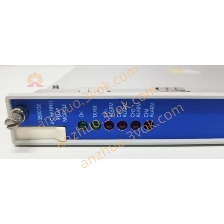
3500/32
Description
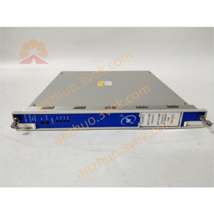
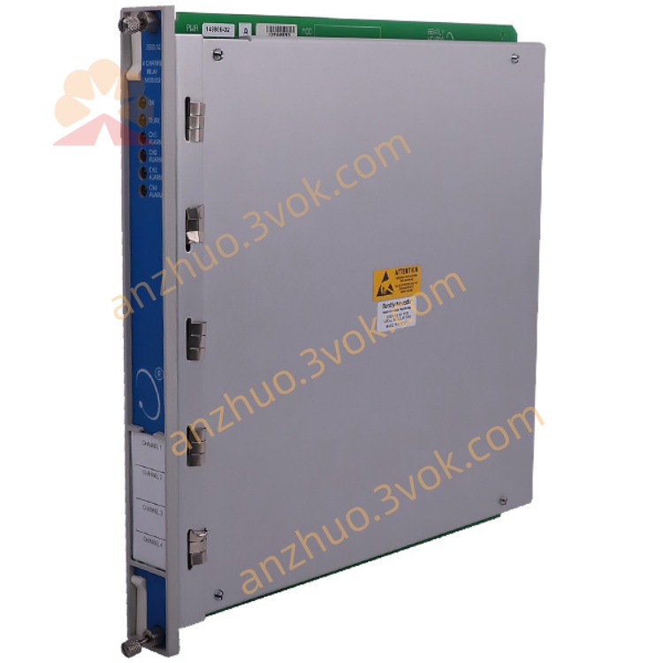
3500/32 (Bentley 4-channel relay module)
Model: 3500/32 (Common model: 3500/32-01-02, Spare part number: 184631-02)
Brand: Bently Nevada
Series: 3500 Mechanical Protection System (TSI)
Position: Full-height 4-channel relay output card, providing programmable alarm/danger relay contacts for the 3500 system, directly driving audible and visual alarms, shutdown circuits or connecting to DCS/PLC, is the core execution output component of the vibration protection system.
I. Basic Parameters
1. Electrical and Power Consumption
Power Supply: 3500 chassis backplane + 5 VDC
Power Consumption: 5.8 W (typical)
Relay Type: SPDT (Single-Pole Double-Throw), each channel includes COM/NO/NC
Contact Capacity: 5 A @ 24 VDC / 120 VAC; 1 A @ 240 VAC (resistive)
Action Time: < 10 ms
Arc Suppression: Built-in 250 Vrms arc extinguisher, extending contact lifespan
2. Environmental and Mechanical
Operating Temperature: -30 °C ~ +65 °C
Storage Temperature: -40 °C ~ +85 °C
Relative Humidity: 5%–95% (no condensation)
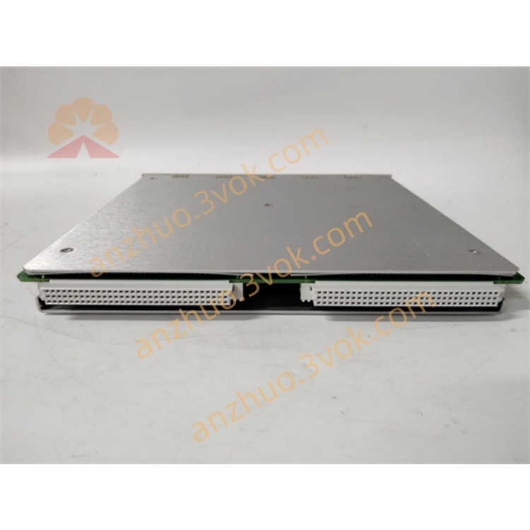
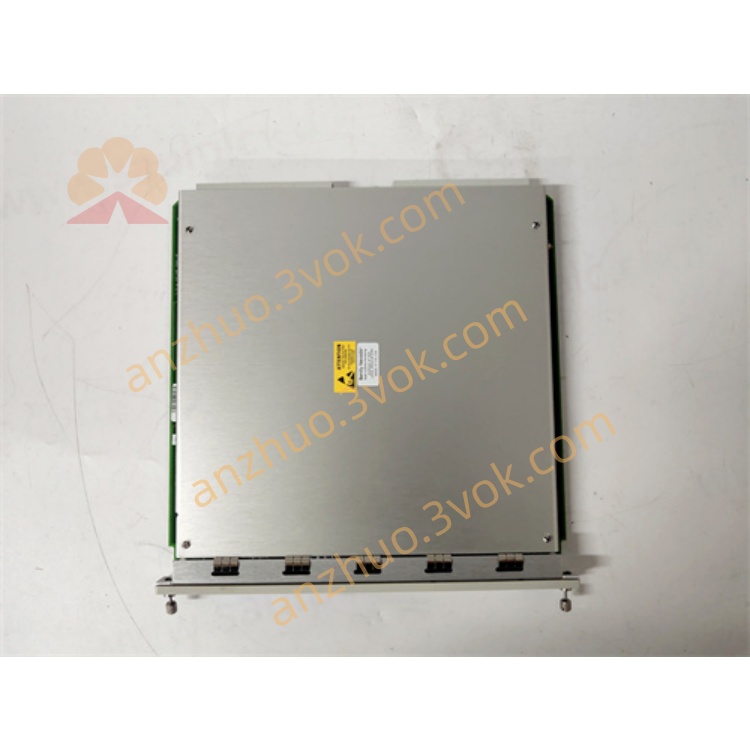
Size (Height × Width × Depth): 241.3 × 24.4 × 99.1 mm (full-height module)
Weight: Approximately 0.4 kg
Installation: Any full-height slot of 3500 chassis (slots 3–15)
3. Status Indicator Lights (Panel)
OK (Green): Module operating normally
RLY1–RLY4 (Yellow): Corresponding relay actions (on = attracted)
II. Core Functions
4 Independent Relay Outputs: Each channel can be independently programmed and mapped to the ** Alert / Danger / Not OK ** status of any monitoring card (3500/40M/42M/45M, etc.).
Programmable Logic (Core):
Support AND/OR voting logic (e.g., "Axis vibration high AND displacement high → trigger shutdown")
Each channel can be set to normal excitation / power failure excitation (the safety shutdown option selects "power failure excitation" first)
Support Self-Release (Latch): Maintains the state after triggering, can be manually / remotely reset
System-level Interconnection: Can combine logic across channels and modules to implement complex protection strategies (such as vibration + temperature + rotational speed three-parameter interlock).
Alarm Levels:
Alert (Warning): Drive alarm lights / buzzer
Danger (Danger): Drive shutdown circuit (electromagnet valve, circuit breaker)
Redundant Expansion: 4 channels per module, multiple modules can be paralleled to expand channels; critical systems can be equipped with 3500/34 triple redundant relay modules.
III. Model Code (3500/32-XX-XX) Table
Section Code Explanation
1 01 Relay output: Standard SPDT
2 02 Logical version: Supports advanced voting logic
IV. Installation and Wiring
1. Installation location
Full-height slot of 3500 rack (Slot 2 is 3500/22M, starting from Slot 3, 3500/32 can be installed)
A single rack can accommodate up to 8 pieces (32 relays)
2. Backplane wiring (terminal block)
RLY1–RLY4: Each channel COM/NO/NC
COM: Common terminal
NO: Normally open (conducts when the relay is attracted)
NC: Normally closed (conducts when the relay releases)
Wiring suggestions:
Strong current circuits (>24 VAC) connected with a 3 A fuse
Shielded wire single-ended grounding, away from strong interference from the inverter/motor
V. Configuration Steps (Quick)
Hardware installation: Power off, insert into full-height slot, power on, OK light should be constantly on.
Software configuration:
Open 3500 System Configuration Software, connect the rack.
Enter 3500/32 configuration page, define the logic for each relay channel:
Mapping channel (such as 3500/42M CH1 vibration danger)
Logic type (AND/OR)
Excitation mode (Normal/Energized)
Self-retention (Latch)
Configuration download: Configure and download to the rack, it takes effect after automatic restart.
Function test: Simulate channel over-limit, corresponding RLY light should be on, measure the contact on-off.
VI. Common Faults and Maintenance
OK light off: Poor contact (unplug and clean the gold fingers), configuration error (re-download configuration), hardware damage (replace the module).
Relay does not operate: Logical mapping error, excitation mode set in reverse, contact burnout (replace the module).
Contact sticking: Overload, frequent operation → Check the load capacity, reduce the number of operations.
Regular maintenance: Check the indicator lights and wiring terminals every quarter; modules are maintenance-free, faults can be directly replaced with spare parts.
Get a Quote